
Rural fish control circuit

The electronic schematic for the fish farming system with an oxygen controller is designed to optimize the operation of both the oxygen and circulating pumps, ensuring efficient use of energy while maintaining the health of the aquatic environment. The power circuit is initiated through a manual switch (S), which connects to a transformer (T) that steps down the AC voltage from 220V to a lower voltage suitable for the control circuit. The rectifier diodes (VD1-VD4) convert the AC voltage to DC, which is then smoothed by the filter capacitor (C1) to provide a stable 24V DC power supply.
In the control circuit, the transistors (VT1 and VT2) serve as switches that control the flow of current to the relays (K1 and K2). The operation begins with the charging of capacitor C2, which is influenced by the voltage across it. Once the voltage reaches a predetermined level, VT1 conducts, activating relay K1, which in turn allows capacitor C3 to charge. The charging of C3 is crucial as it determines the timing for switching the operation of the pumps. When C3 reaches its threshold, VT2 activates relay K2, switching the power from the oxygen pump to the circulating pump.
This cyclical operation continues, with the system alternating between adding oxygen and circulating water, thus maintaining optimal conditions for the tropical fish. The design allows for flexibility in timing adjustments, enabling the user to modify the resistance and capacitance values to suit specific aquaculture needs. This ensures that the fish farming setup is not only energy-efficient but also promotes a sustainable environment for the fish to thrive.Artificial hatching or breeding tropical fish, while watching the fish pond need to configure add oxygen pump and circulating pump. Plus oxygen pump and circulating pump long-t erm continuous work not only wastes energy, but also easy to damage the parts. This example describes the fish farming with oxygen controller can control is applied between the oxygen pump and circulating pump rest cycle work, intermittent pond to add oxygen and water, with energy and extend equipment life role. (1) The circuit fish farming with oxygen controller circuit from the power circuit and control circuit, as shown in FIG.
Power circuit from the power switch S, the power transformer T, rectifier diode VD1 ~ VD4 and filter capacitor Cl composition. Coat control circuit consists of transistors VT1, VT2, relay Kl, K2, resistance Ri --R4, capacitors C2, G and diodes VD5, VD6 composition.
(2) circuit schematic power switch S, AC 220V voltage by T Buck, VD1-VD4 rectification and Cl filtered to produce 24V DC voltage supply control circuit. At this point AC 220V voltage by K2-2 normally closed contacts are circulating pump power to run work.
+ 24V voltage through R. K1 and normally closed contacts Kl-l charging C2. When the voltage G reaches a certain value, the transistor, rri guide, relay Kl pull its normally open contact K1-2 connected. + 24V voltage by R3 and Kl-2 contact pairs C3 charging {Meanwhile, the normally closed contacts Kl-l disconnect, C2 stop charging, the voltage on C2 discharge through R2 to VT1, VT1 maintain conduction.
Kl remains Ai engaged state. When the voltage on C3 reaches a certain value. vr2 conduction. K2 pull, K2-1 normally closed contact off, cut off the island of discharge circuit, VT1 deadline. Kl release, C2 fork to start charging. Meanwhile, K2-2 normally open contact connected, plus oxygen pump power work, circulating pump stopped working. When 0 is charged to a certain value, VT1 and conduction, Kl pull, C3 charge, followed by VT2 conduction, K2 pull, circulating pumps and power work, plus oxygen pump to stop working.
So the cycle, plus achieve intermittent oxygen pump and circulating pump cycle work. Tone Rang R, ink resistance or change C2, C3 capacity, plus adjustable intervals and circulating pump oxygen pump intermittent work.
Related Circuits
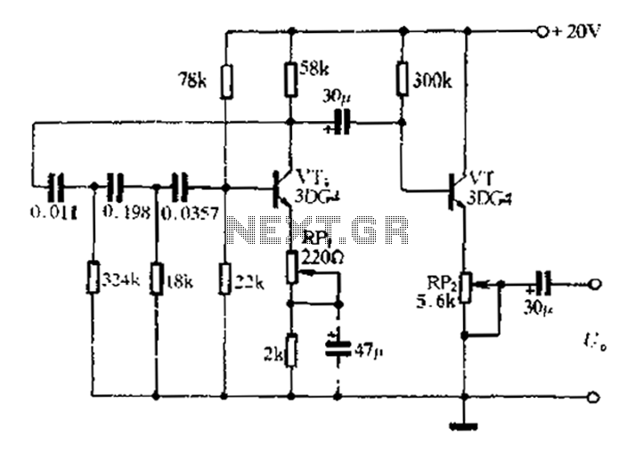
1 kHz RC phase shift oscillator circuit The 1 kHz RC phase shift oscillator circuit is designed to generate a continuous sine wave output at a frequency of 1 kHz. This circuit typically utilizes a combination of resistors and capacitors...
This circuit functions with inaudible (ultrasonic) sound. Sound of frequency up to 20 kHz is audible to human beings. The sound of frequency above 20 kHz is called ultrasonic sound. The circuit described generates (transmits) ultrasonic sound of frequency...
To achieve a low-cost, accurate, and simple position control system, a stepper motor can be utilized. A circuit designed to drive the motor should be mounted in proximity to the motor itself. Stepper motors are widely employed in applications requiring...
To complement the 60 Watt MOSFET audio amplifier, a high-quality preamplifier design was necessary. A discrete components topology using +24V and -24V supply rails was chosen, minimizing the transistor count while still achieving low noise, very low distortion, and...

An audio power amplifier circuit for a 3-watt stereo amplifier using the MAX 7910 IC is explained below. The audio power amplifier circuit utilizing the MAX 7910 IC is designed to deliver a maximum output power of 3 watts per...
This is a voltage converter designed to output a voltage range of ±1.25 to ±30V from an input voltage of ±35V. A three-terminal voltage regulator is utilized to achieve the desired voltage transformation in this unit. The voltage converter employs...