
Safe Oscillator For Watch Crystals

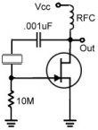
The circuit in question is a CMOS oscillator that integrates a watch crystal, typically used in timekeeping applications, into a higher voltage system. The primary function of the circuit is to ensure that the crystal operates within its safe voltage limits while still being part of a 12V powered system.
The inclusion of two LEDs serves a dual purpose: they not only provide an indication of the oscillator's operational status but also contribute to the voltage regulation needed for the crystal. When the circuit is powered, the LEDs will light up, confirming that the oscillator is active and functioning as intended. The use of a 470nF capacitor (C3) is critical in this design, as it acts as a voltage limiter, preventing the crystal from experiencing excessive voltage that could lead to failure.
Capacitors C1 and C2 are also integral to the circuit's performance. Their values must be selected carefully to ensure that the oscillator starts reliably and maintains stable oscillation. Adjustments to these capacitors may be necessary depending on the specific characteristics of the crystal used. However, it is essential to keep the ratio between C1 and C2 consistent to maintain the desired oscillation frequency and stability.
The loading effect of the higher capacitance values for C1 and C2 will cause the oscillator to operate at a frequency lower than the crystal's specified frequency of 32.768 kHz. This is an important consideration for applications requiring precise timing, as it may affect the overall performance of the circuit in timekeeping functions. Proper design and component selection are crucial to achieving the desired operational characteristics while ensuring the longevity and reliability of the crystal within the circuit.This circuit was developed to allow watch crystals to be used in an existing CMOS oscillator circuit that was to run from a 12V supply. The problem is that these crystals only work up to a supply voltage of about 6V. Any more than that and the crystal will be over-driven, causing it to shatter. This circuit solves the problem by using LEDs 1 & 2 a nd a 470nF capacitor (C3) to limit the drive to the crystal to about 4V peak-to-peak. Note that it may be necessary to adjust C1 & C2 to ensure reliable start-up and stable oscillation with some crystals. However, the C1:C2 ratio should be maintained. As a bonus, the two LEDs both glow, giving a visual indication that the oscillator is working. The relatively high values used here for capacitors C1 & C2 will load the crystal, which means that the oscillator will run at less than the nominal crystal frequency (32.
768kHz). 🔗 External reference
Related Circuits
The major functional blocks necessary for designing a general-purpose audio oscillator are outlined, along with the details of the current prototype. The implementation is in the mode of an analog computer, as the desired outputs are sine and cosine...
Many RC oscillators utilize an advanced circuit in the phase shift unit. This configuration employs a voltage feedback amplifier, which experiences a significant decline in gain at higher frequencies, leading to the cessation of oscillation before achieving the desired...
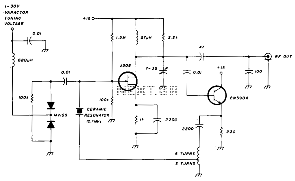
There is a significant amount of vintage amateur equipment that many enthusiasts have chosen to restore and rejuvenate. Although many early amateur transceivers operate effectively, they typically lack a digital readout and depend on analog dials for tuning. The...
A Pierce Oscillator is a type of oscillator that utilizes a crystal instead of a parallel-resonant circuit (LC circuit). This oscillator also employs the voltage developed from a tap between two capacitors in the tank circuit. Both Pierce Oscillators...
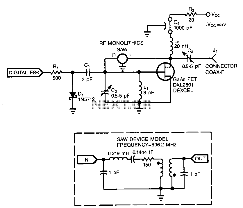
Adding a diode, a resistor, and a capacitor to the surface-acoustic-wave (SAW) oscillator enables its use in frequency-shift-keying (FSK) applications. The diode (D1), resistor (R1), and capacitor (C1) create a simple diode switch where D1 shunts C1 to ground....
The FET input amplifier utilizes fixed bias with source feedback, resulting in a very high input impedance and low capacitance. An emitter follower is driven by the FET amplifier, which, despite its low output impedance, feeds a transformer with...