
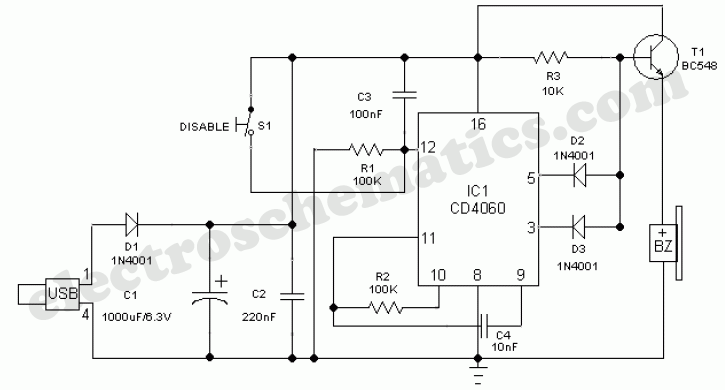
safety guard

The circuit employs an oscillator to manage the timing sequence that protects appliances from sudden power surges. The key component, the CD4060 IC, serves both as an oscillator and a frequency divider, generating a clock signal that drives the blinking of LED D5. This visual indicator provides a clear status of the circuit during the delay period.
Once the three-minute delay elapses, the output Q14 transitions to a high state. This change is crucial as it activates the gate of the silicon-controlled rectifier (SCR) via diode D4. The SCR acts as a switch that controls the high voltage supplied to the appliance. When triggered, the SCR allows current to flow from the anode to the cathode, thus energizing the relay coil. The relay, in turn, closes its contacts, allowing the appliance to operate safely.
The inclusion of D6 serves as an additional indicator, confirming that the appliance is now powered. The switch SW1 is a user-friendly feature that allows for immediate operation of the appliance without waiting for the three-minute countdown, providing flexibility in usage.
Overall, this time delay circuit not only protects appliances from voltage spikes but also offers a controlled startup sequence, enhancing the longevity and reliability of the connected devices.Protect your home appliances from voltage spikes with this simple time delay circuit. Whenever power to the appliances is switched on or resumes after mains failure, the oscillator starts oscillating and D5 blinks. This continues for three minutes. After that, Q14 output of IC CD4060 goes high to trigger the gate of the SCR through D4. At this moment, the voltage is available at the cathode of the SCR, which energizes the relay coil to activate the appliance and D6 glows.
Switch SW1 is used for quick start without waiting for delay.. 🔗 External reference
Related Circuits
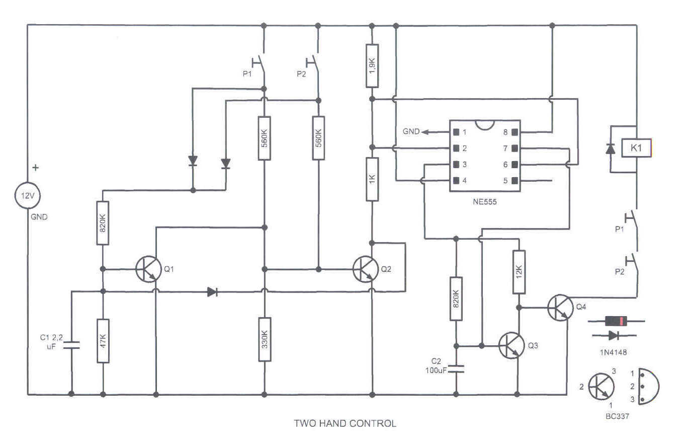
This circuit turns on a relay when two buttons are pressed at the same time. The relay backs off after a few seconds, then the buttons have to be released and pressed again. This feature is often required in...
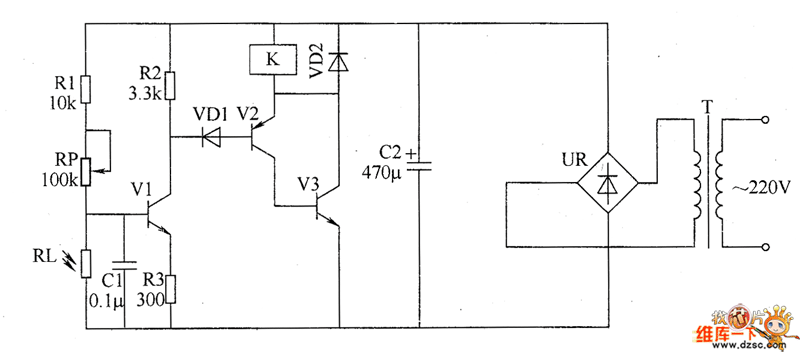
The optical safety switch circuit includes a power supply circuit, a light control circuit, and a control implementation circuit (switch circuit). The power circuit is made up of a power transformer (T), a bridge rectifier (UR), and a filter...
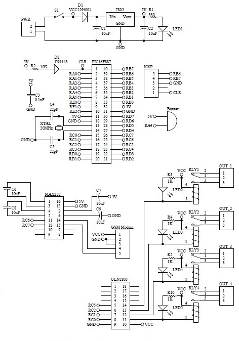
How to turn on equipment by sending SMS `1111` to switch it ON and switch off the equipment by sending SMS `0000`. The GSM switch will receive instructions for either load 1 (L1), load 2 (L2), load 3 (L3),...

This circuit provides protection for telephones, EPABX systems, telephone modems, and similar devices against lightning discharges and line voltage spikes. It incorporates a safety capacitor and gas discharge components. The circuit employs a safety capacitor to filter out high-frequency noise...
This simple circuit can be used to protect a bike from theft. It produces a loud alarm tone if someone attempts to start the bike. The alarm can only be disabled when the hidden switch S2 is opened. The...
An emergency light is a light source designed to be available during emergencies. It operates automatically and is powered by a rechargeable battery. An emergency light system typically consists of several key components: a light source, a rechargeable battery, a...