
A Simple Capacitance Multiplier Power Supply For Class-A Amplifiers

The Class-A amplifier is a type of electronic amplifier that conducts over the entire range of the input signal cycle, offering high fidelity and linearity. However, it requires a power supply that minimizes ripple voltage to ensure optimal performance. The use of a regulated power supply is essential for maintaining the stability and quality of the output signal.
A capacitance multiplier filter is often employed in this context to reduce ripple voltage. This circuit essentially uses a combination of resistors, capacitors, and transistors to increase the effective capacitance seen by the load, thereby smoothing out variations in the power supply voltage. The basic topology includes an input capacitor connected to the power supply, followed by a transistor configured to amplify the capacitance effect of a smaller capacitor connected to the output.
To enhance the performance of the capacitance multiplier, several improvements can be implemented. First, ensuring that the transistor used has a low output impedance can significantly reduce the output ripple. Additionally, selecting high-quality capacitors with low equivalent series resistance (ESR) will further diminish ripple effects. The layout of the circuit is also critical; minimizing the distance between the capacitors and the load can help reduce inductive effects which may introduce noise.
Furthermore, incorporating a feedback loop in the design can help regulate the output voltage more effectively, allowing for better performance across varying load conditions. This can be achieved by using an operational amplifier that monitors the output voltage and adjusts the base voltage of the transistor accordingly to maintain a constant output level.
Overall, while the provided schematic serves as a foundation, careful consideration of component selection, circuit layout, and additional features can significantly enhance the performance of the Class-A amplifier power supply.Since I have provided the schematic for John L Linsley-Hood`s Class-A amplifier, I felt that some readers may wish to experiment with the concept. Unfortunately, a very low ripple power supply is needed for all Class-A amps, and the most common solution is to use a regulated supply.
A basic circuit is provided in the article, but it is assumed that the builder knows all the pitfalls. The supplied schematic is in fact for a capacitance multiplier filter (not a regulator), but is somewhat lacking (I feel) and can be improved dramatically.
🔗 External reference
Related Circuits
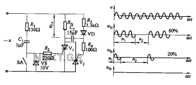
The output waveform of the thyristor zero trigger circuit is a sine wave, which does not generate electromagnetic interference like a phase-shift trigger circuit. This circuit serves as a basic thyristor power adjustment mechanism. In the circuit diagram, the...
The TDA7294 amplifier module is a monolithic integrated circuit designed for use as an audio class AB amplifier in hi-fi applications. It has a wide voltage range and output current capability, enabling it to supply the highest power into...
A Tesla Coil can be understood as a high-power radio frequency transmitter with an inefficient antenna. The secondary coil functions as a significantly shortened quarter-wave antenna. The Tesla Coil is an electrical resonant transformer circuit that is designed to produce...
PWM rectifier power controller power supply. Visit the page to read the explanation about the associated circuit diagram. A PWM (Pulse Width Modulation) rectifier power controller is a sophisticated electronic circuit designed to convert alternating current (AC) to direct current...
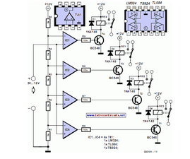
This circuit demonstrates that microprocessors, personal computers, and the latest ultra-accurate digital-to-analog converters (DACs) are excessive for the task of sequentially controlling four relays. The circuit utilizes a simple microcontroller or a basic timer IC to manage the operation of...
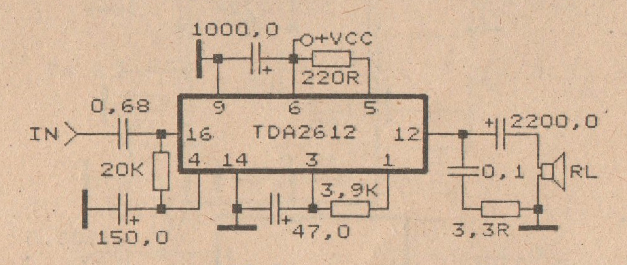
This amplifier circuit is based on the IC TDA2612 produced by Siemens. The minimum voltage required for this circuit is 10 volts, while the maximum voltage is 35 volts DC. The power output is 25 watts with a 4-ohm...