
Ultrasonic range finder circuit

The circuit utilizes a PIC12C508 microcontroller, which acts as the central control unit, managing the timing and signal generation for the ultrasonic transducer. The transducer operates at a frequency of 40 kHz, which is optimal for detecting objects within the specified range. The choice of a 5V drive from the PIC is practical for larger objects, but for improved sensitivity, a higher voltage drive is employed through the MAX232. This IC converts the logic levels and provides a higher output voltage, enhancing the transmission capabilities of the piezo transducer.
The two-stage op-amp configuration, using an LM1458, amplifies the received signals. The careful selection of gain stages ensures that the circuit can discern echoes from nearby objects while minimizing the impact of direct coupling. The LM311 comparator plays a crucial role in converting the analog amplified signal into a digital output, with hysteresis implemented to prevent false triggering from noise.
The design addresses the challenge of residual vibrations from the transducer by timing adjustments and threshold modifications. By controlling the detection window and managing the timing of the echo pulse, the circuit effectively distinguishes between the echo and unwanted signals. The integration of capacitors for voltage stabilization and filtering helps maintain performance consistency, even in the presence of noise generated by the MAX232.
Overall, this circuit is a robust solution for ultrasonic distance measurement, combining cost-effectiveness with reliability and precision in object detection across varying distances. The design allows for flexibility in application while ensuring accurate performance, making it suitable for various electronic projects and sensor applications.The circuit is designed to be low cost. It uses a PIC12C508 to perform the control functions and standard 40khz piezo transducers. The drive to the transmitting transducer could be simplest driven directly from the PIC. The 5v drive can give a useful range for large objects, but can be problematic detecting smaller objects. The transducer can hand le 20v of drive, so I decided to get up close to this level. A MAX232 IC, usually used for RS232 communication makes and ideal driver, providing about 16v of drive. The receiver is a classic tw1o stage op-amp circuit. The input capacitor C8 blocks some residual DC which always seems to be present. Each gain stage is set to 24 for a total gain of 576-ish. This is close the 25 maximum gain available using the LM1458. The gain bandwidth product for the LM1458 is 1Mhz. The maximum gain at 40khz is 1000000/40000 = 25. The output of the amplifier is fed into an LM311 comparator. A small amount of positive feedback provides some hysterisis to give a clean stable output. The problem of getting operation down to 1-2cm is that the receiver will pick up direct coupling from the transmitter, which is right next to it.
To make matters worse the piezo transducer is a mechanical object that keeps resonating some time after the drive has been removed. Up to 1mS depending on when you decide it has stopped. It is much harder to tell the difference betw1een this direct coupled ringing and a returning echo, which is why many designs, including the Polaroid module, simply blank out this period.
Looking at the returning echo on an oscilloscope shows that it is much larger in magnitude at close quarters than the cross-coupled signal. I therefore adjust the detection threshold during this time so that only the echo is detectable. The 100n capacitor C10 is charged to about 6v during the burst. This discharges quite quickly through the 10k resistor R6 to restore sensitivity for more distant echo`s.
A convenient negative voltage for the op-amp and comparator is generated by the MAX232. Unfortunately, this also generates quite a bit of high frequency noise. I therefore shut it down whilst listening for the echo. The 10uF capacitor C9 holds the negative rail just long enough to do this. In operation, the processor waits for an active low trigger pulse to come in. It then generates just eight cycles of 40khz. The echo line is then raised to signal the host processor to start timing. The raising of the echo line also shuts of the MAX232. After a while no more than 10-12mS normally, the returning echo will be detected and the PIC will lower the echo line. The width of this pulse represents the flight time of the sonic burst. If no echo is detected then it will automatically time out after about 30mS (Its tw1o times the WDT period of the PIC).
Because the MAX232 is shut down during echo detection, you must wait at least 10mS betw1een measurement cycles for the /- 10v to recharge. Performance of this design is, I think, quite good. It will reliably measure down to 3cm and will continue detecting down to 1cm or less but after 2-3cm the pulse width doesn`t get any smaller.
🔗 External reference
Related Circuits
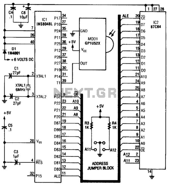
This circuit is based on the Sharp GP1U52X infrared module and the 1NS8048L microprocessor. The GP1U52X is a hybrid integrated circuit and infrared detector that provides a strong, clean signal for subsequent filtering and demodulation. The circuit utilizes the Sharp...
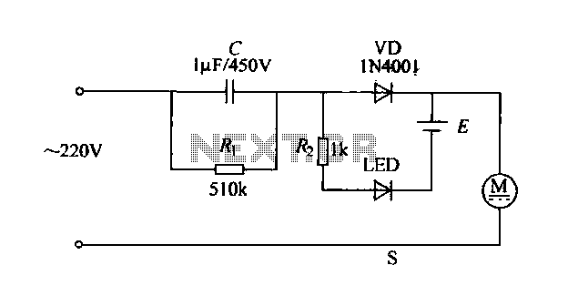
The electric shaver circuit is illustrated in Figure 1-17. It features a buck capacitor (C) rated at 1 µF and 450V, which connects through diode VD to charge 1.2V nickel-cadmium batteries. Additionally, after the buck converter, there is a...
This is a three-band equalizer circuit, specifically a tone control circuit that utilizes a single operational amplifier (op-amp) and features three adjustable frequency ranges: bass, midrange, and treble. The three-band equalizer circuit employs an operational amplifier to achieve tone control...
A small electronic switch connects a battery to equipment for a specific duration when a push-button is momentarily pressed. The circuit also considers ambient light levels; when it is dark, the display cannot be read, so it is logical...
This is a 3 Band Equalizer circuit designed to control the treble, midrange, and bass frequencies. The circuit utilizes a single operational amplifier (op-amp). The 3 Band Equalizer circuit serves to enhance audio signals by allowing users to adjust specific...
Are you unfamiliar with the basics of electronics? An online store has recently opened, offering four excellent books on basic electronics for sale. Reviews of these books are available, and purchases can be made as desired. These books are...