
Schematics Low-Ripple Power Supply
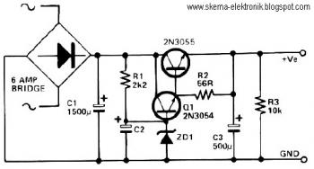
This circuit configuration is particularly advantageous for applications where a stable output voltage is crucial, and the ability to handle high current loads with minimal voltage fluctuations is necessary. The Darlington pair configuration of Q1 and Q2 allows for significant current amplification, which is essential in driving heavy loads typically encountered in audio amplification scenarios. The choice of ZD1 is critical, as it sets the operating point for Q1, ensuring that the transistor operates within its optimal range for linearity and efficiency.
The reference voltage provided by ZD1 and R1 must be carefully calculated to ensure that Q1 remains in the active region, preventing distortion in the output signal. The selection of C2 is also vital; a larger capacitance will yield better smoothing of the output voltage, reducing ripple. The effective capacitance can be adjusted by varying C2, thereby influencing the overall performance of the amplifier. This adaptability allows for fine-tuning of the circuit to meet specific performance criteria, making it suitable for high-fidelity audio applications.
In summary, this circuit design effectively combines the advantages of a Darlington transistor configuration with careful voltage regulation and capacitance selection, resulting in a robust solution for high-current, low-ripple voltage applications such as high-powered Class AB amplifiers.This circuit can be used where a high current is required with a low-ripple voltage (such as in a high-powered class AB amplifier when high-quality reproduction is necessary). Q1, Q1 and R2 can be regarded as a power Darlington transistor. ZD1 and R1 provide a reference voltage at the base of Q1. ZD1 should be chosen thus: ZD1=Vout-1. 2. C2 can be chosen for the degree of smoothness as its value is effectively multiplied by the combined gains of Q1/Q2, if 100uF is chosen for C2, assuming minimum hfe for Q1 and Q2, C=100x15(Q1)x25(Q2)=37, 000uF. 🔗 External reference
Related Circuits
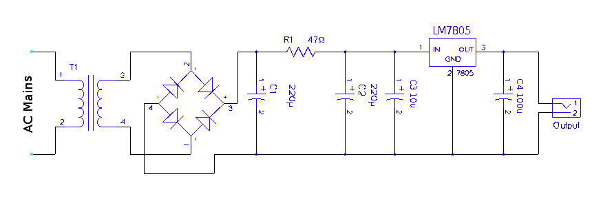
A regulated 5-volt DC supply is essential for powering microcontroller and TTL-based circuits. The output of most wall adapters is often too rippled and impure for use in digital circuits. An inexpensive power supply can be constructed using discrete...
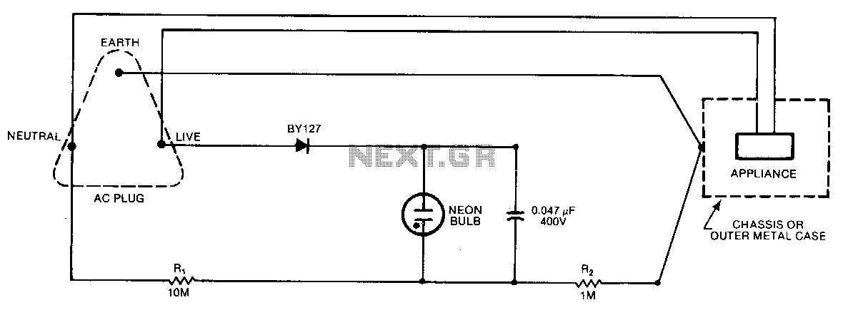
A continuous glow signifies that everything is normal; a blinking or extinguished neon bulb indicates a broken earth or ground connection, or interchanged neutral and live wires. In electronic circuits, a neon bulb is often used as an indicator light...
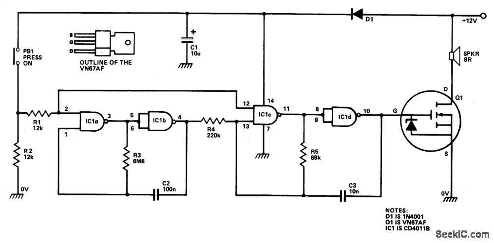
IC1a and IC1b are configured as a slow astable multivibrator, while IC1c and IC1d are set up as a fast astable multivibrator. Both configurations are of the "gated" type, allowing them to be activated or deactivated through push button...
The TDA7294 amplifier module is a monolithic integrated circuit designed for use as an audio class AB amplifier in hi-fi applications. It has a wide voltage range and output current capability, enabling it to supply the highest power into...
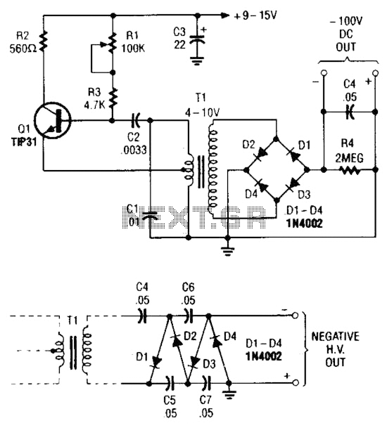
The combination of a Hartley oscillator and a step-up transformer can generate significant negative high voltage, particularly when the voltage output of the transformer is multiplied by the circuit. The Hartley oscillator is a type of LC oscillator that utilizes...
Power diagram videos for a DIY solar panel system wiring diagram. This is an exact diagram of the power window wiring diagram available in printed books on Amazon, covering power door locks and wiring diagrams. The provided description outlines a...