
power diagram

The provided description outlines a power diagram relevant to DIY solar panel systems, emphasizing the importance of proper wiring for efficient operation. The solar panel system typically consists of solar panels, a charge controller, batteries, and an inverter. The wiring diagram serves as a crucial guide for connecting these components effectively.
In a typical solar panel system, solar panels convert sunlight into direct current (DC) electricity. This DC electricity is then routed to a charge controller, which regulates the voltage and current coming from the solar panels to prevent overcharging the batteries. The batteries store the energy generated and provide power when sunlight is not available.
The inverter is responsible for converting the stored DC electricity from the batteries into alternating current (AC) electricity, which is used to power household appliances. The wiring diagram must clearly indicate the connections between the solar panels, charge controller, batteries, and inverter, ensuring that all components are connected correctly to prevent damage and ensure optimal performance.
Additionally, the power window wiring diagram mentioned may illustrate the electrical connections for power windows in vehicles, showcasing how each component, such as switches and motors, is interconnected. This diagram is essential for automotive applications, allowing for troubleshooting and repair of power window systems.
Overall, a comprehensive wiring diagram is vital for both solar panel systems and automotive power window systems, ensuring that users can safely and effectively implement and maintain these electrical systems.Power Diagram Videos DIY Solar Panel System Wiring Diagram. This is an exact diagram how Power Window Wiring Diagram 1 Amazon Printed Books Power Door Locks & Wiring Diagram Amazon Printed Books.. 🔗 External reference
Related Circuits
This is a low-power voltmeter circuit suitable for alternative energy systems operating on 12-volt and 24-volt batteries. The voltmeter features an expanded scale design, allowing it to display small voltage increments within the 10 to 16-volt range for 12-volt...
The following circuit illustrates the connection of the Devantech SRF04 Ultrasonic Sensor to the SV203 powered PPRK Circuit Diagram. This circuit is based on the Devantech SRF04 sensor and features a minimum initiation time of 10 milliseconds for the...
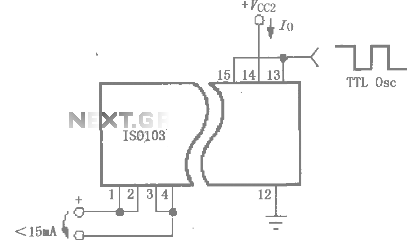
This circuit is designed to reduce power consumption in an ISO103 application. It operates with a Vcc1 current of less than 15mA for multi-channel synchronous applications. An oscillator, as illustrated in the figure, can be utilized to generate a...
Each part of the LCD has an individual counter, latch, decoder, and driver. The pumping signal is fed back to the motherboard of the LCD. When the display section is disconnected, the phase and amplitude of the motherboard and...

In the example above, a low voltage (12V DC) is utilized to activate a relay that switches a 240V AC main circuit. It is important to note that there is no electrical connection between the two circuits within the...
This is a heavy diet, which can deliver 10A stabilized. The circuit is built around a normal 78xx controller, but for extra power equipped with T1. For the 78xx can be taken any type. Keep in mind that the...