
V-shaped torque motor speed control circuit

The circuit in question employs two single-phase voltage regulators, which are crucial for maintaining a stable output voltage despite variations in load or input voltage. These regulators are arranged in a V-shaped configuration, optimizing the layout for efficient voltage regulation and balance. The design facilitates the simultaneous adjustment of two parameters: the voltage output and the balance of the system, ensuring that both aspects can be fine-tuned for optimal performance.
The regulators operate by utilizing feedback mechanisms that monitor the output voltage and make necessary adjustments to maintain the desired level. This is particularly important in applications where precise voltage levels are critical for the operation of other electronic components. The V-shaped arrangement enhances the thermal management of the regulators, as heat dissipation can be effectively managed across the layout.
Furthermore, the circuit's ability to achieve a performance level comparable to a three-phase balanced adjustment is noteworthy. This characteristic is particularly beneficial in applications where three-phase systems are not feasible or where a simpler single-phase solution is preferred. The symmetrical design allows for a balanced output across the regulators, minimizing the risk of voltage imbalances that could lead to inefficiencies or potential damage to connected loads.
In summary, the circuit presented in Figure 3-177 represents an innovative approach to voltage regulation, effectively combining the advantages of single-phase voltage regulators with a configuration that allows for enhanced balance and performance. The ability to adjust both voltage and balance simultaneously makes this circuit a versatile solution for various electronic applications. Circuit shown in Figure 3-177. It uses two single-phase voltage regulator and connected to a V-shaped, single-phase regulators when two concentric series of time-linked slippag e u and w simultaneously symmetrical slide, you can adjust the balance, with the same performance three-phase balanced adjustment .
Related Circuits
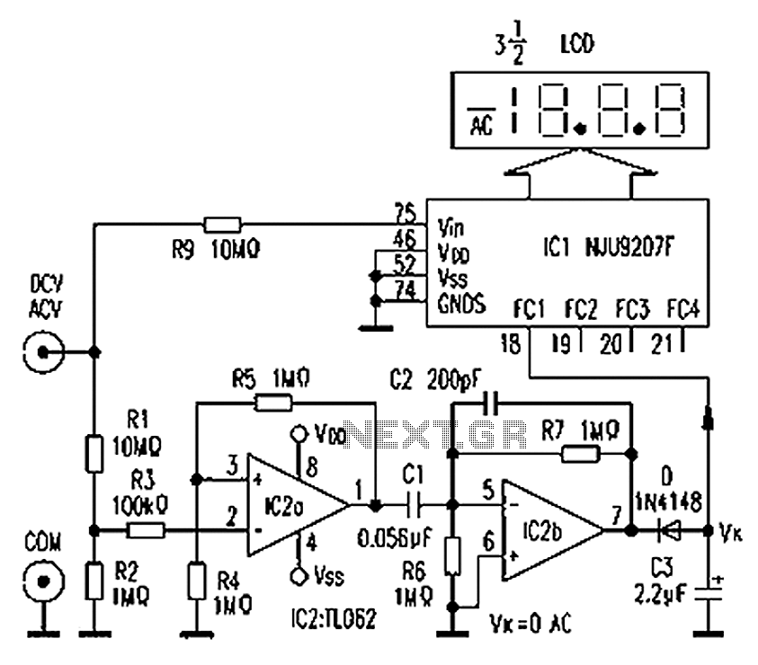
The circuit depicted in the figure illustrates an automatic AC/DC converter for a digital multimeter. Typically, standard digital multimeters require manual intervention to switch between AC and DC measurements. The new DT860D digital multimeter utilizes the NJU9207F automatic range...
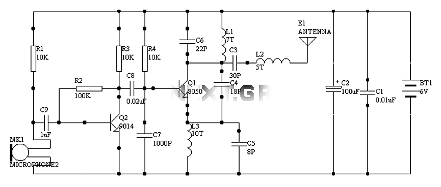
1000 m single-tube FM transmitter circuit diagram of oscillation. The circuit diagram for a 1000 m single-tube FM transmitter is designed to generate frequency modulation signals suitable for transmission over a distance of approximately 1000 meters. This transmitter employs...
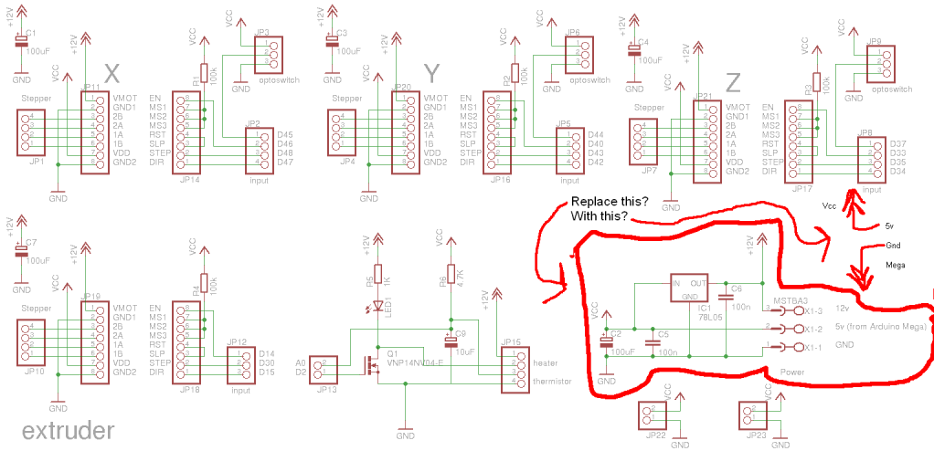
Preparing to assemble Adrian's Pololu stepper driver circuit has raised a question. He indicates that if using 5V from the Arduino Mega, the 78L05 voltage regulator should be omitted. This is a positive development, although there is an incorrect...
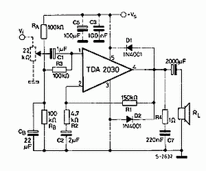
The TDA2030 is a monolithic integrated circuit in a Pentawat® package designed to function as a Class AB audio amplifier. It typically delivers up to 14 watts of output power (with a distortion rate of 0.5%) at 14V with...
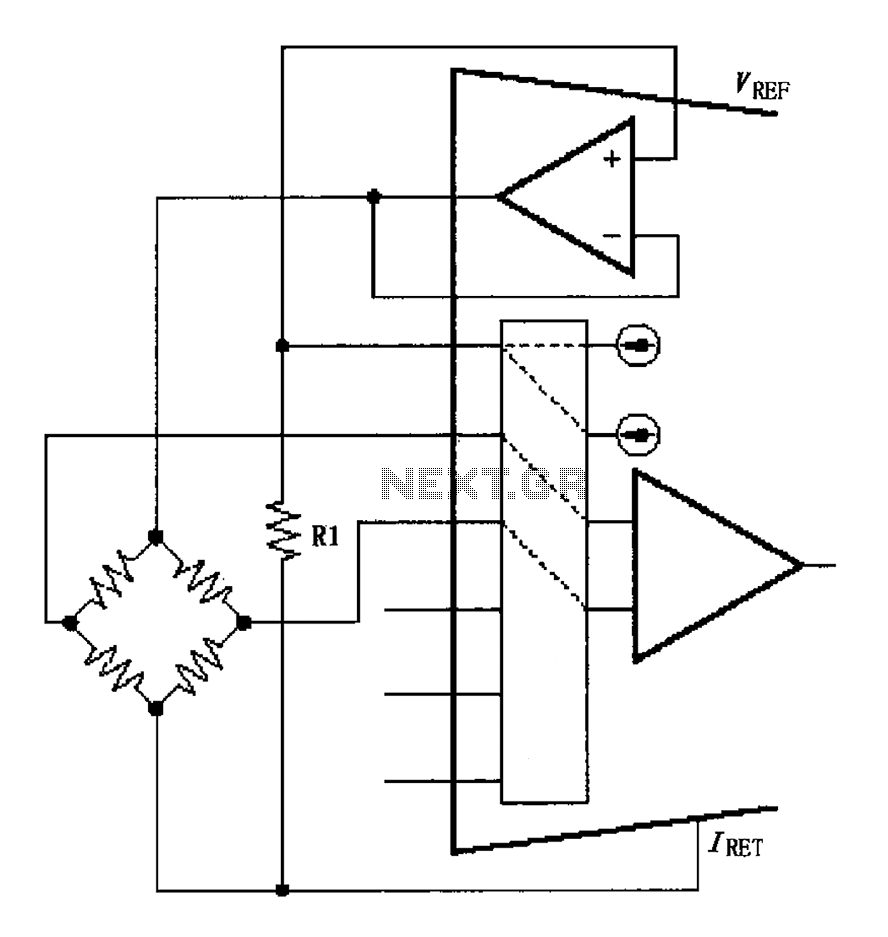
The circuit for the bridge excitation voltage XTR108 is linearized using adjusted algorithms that correspond to the linearization of the RTD response. The excitation voltage VEX is defined as 2IREFR1, where VEX represents the excitation voltage applied at both...
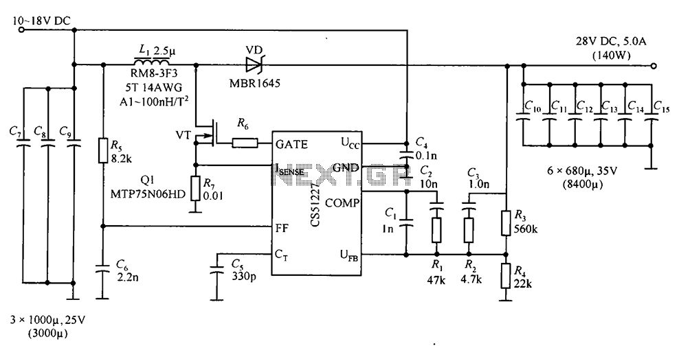
CS51227 is a voltage-type PWM controller that delivers an output of 28V with a maximum current of 5A. The switching frequency is 1.0 MHz, with a starting voltage of 4.7V and a starting current of 75A. The input voltage...