
Screenshot 2.0.0.0 Alpha - CAD Graphic Apps

The electronic schematic for a registry cleaner tool typically includes several key components and functions. At its core, the schematic would feature a microcontroller unit (MCU) responsible for executing the software algorithms that identify and rectify registry errors. The MCU interfaces with a memory module to store temporary data during the scanning process.
The input section of the schematic would include a user interface module, which may consist of buttons and an LCD display for user interaction. This allows users to initiate scans and view results in a straightforward manner. The schematic would also include an input/output (I/O) interface to connect to the computer's registry for reading and writing data.
Power management is crucial in such a device; therefore, a power supply circuit is integrated, ensuring stable voltage levels for the MCU and other components. Additionally, the schematic may feature diagnostic LEDs to indicate the status of the scanning process, providing visual feedback to the user.
The output section would include mechanisms for reporting the results of the scan, such as error codes or success messages, which can be displayed on the user interface. This comprehensive design ensures that the registry cleaner operates efficiently, providing users with an optimized computing experience.This product is amazing. My computer was having issues with the registry. After installing, scanning, and fixing the errors my computer now runs like it is brand new. I would recommend this to others. 🔗 External reference
Related Circuits
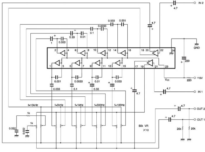
The BA3822 is a five-point stereo graphic equalizer integrated circuit that operates with two channels. Each channel can independently set five center frequencies using external capacitors. This integrated circuit supports a wide operating power supply voltage range (VCC =...
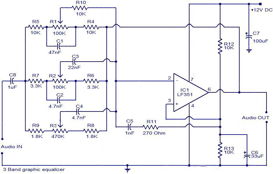
The circuit is a diagram of a simple three-band graphic equalizer circuit. An IC known as the LF351 is utilized in this design. The three-band graphic equalizer circuit is designed to adjust the amplitude of audio signals across three distinct...
The described circuit is a graphic equalizer, characterized by ten adjusting potentiometers. Each of these potentiometers influences a specific frequency range, with the central frequency of each range being an octave (double) away from the central frequencies of adjacent ranges....
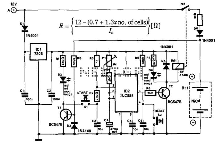
The portable charger is designed primarily for model enthusiasts to charge their NiCad batteries using a car battery outdoors. The circuit's supply voltage is regulated by IC1. When connected to the car battery, LED D2 illuminates only if the...
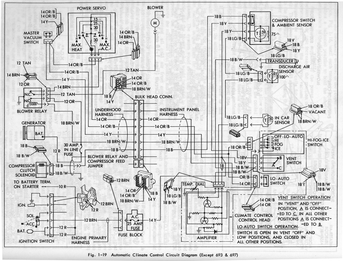
Gerald's 1958 Cadillac Eldorado Seville, 1967 Cadillac Deville, 1967 Eldorado, and 1971 Lincoln Continental Mark III - everything you always wanted to know about these cars. The 1958 Cadillac Eldorado Seville is a classic American luxury vehicle renowned for its...
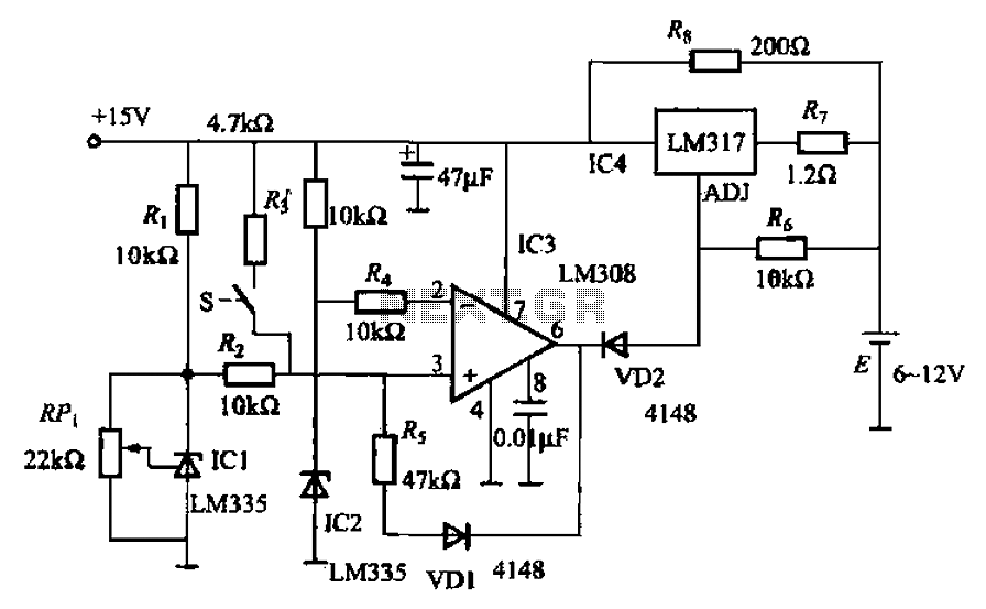
When fast charging a nickel-cadmium battery, the temperature control circuit, as illustrated in the accompanying figure, is designed to monitor the battery temperature to regulate the charging current. The circuit consists of Icl to IC3, which forms the temperature...