
Simple Graphic Equalizer Circuit

The three-band graphic equalizer circuit is designed to adjust the amplitude of audio signals across three distinct frequency bands: bass, midrange, and treble. The LF351 operational amplifier is a key component in this circuit, providing the necessary gain and filtering capabilities.
The circuit typically consists of three separate band-pass filter sections, each tailored to a specific frequency range. The first section addresses the low frequencies (bass), the second targets the mid frequencies, and the third focuses on high frequencies (treble). Each section utilizes resistors and capacitors to set the center frequency and bandwidth, allowing for precise control over the audio signal.
The LF351 IC, being a low-noise, high-speed operational amplifier, is well-suited for audio applications. It is configured in a non-inverting amplifier configuration for each band, ensuring that the output signal maintains the same phase as the input while allowing for gain adjustments through feedback resistors.
The output of each band is then combined, often through a summing amplifier configuration, to produce a final output signal that reflects the adjusted frequency response based on the user’s settings. Controls such as potentiometers may be employed in each band to allow users to increase or decrease the gain for each frequency range, providing a customizable audio experience.
Power supply considerations for the LF351 should also be noted. The IC typically requires a dual power supply, often +15V and -15V, to function properly, ensuring that the output can swing above and below ground.
In summary, the simple three-band graphic equalizer circuit employing the LF351 IC is an effective tool for audio signal processing, allowing for enhanced control over sound characteristics across various frequency bands.The Circuit is the diagram of a simple three band graphic equalizer circuit. An IC called LF 351 IC is used here. 🔗 External reference
Related Circuits
This circuit controls a load, specifically a DC brushless fan, based on a temperature comparison with a setpoint. The transducer utilized is a diode in the forward bias configuration. When forward biased, the forward voltage drop across the diode...
The following circuit illustrates a fully linear diode sensor circuit diagram. This circuit is based on the A748 integrated circuit (IC). Features include the use of an operational amplifier (op-amp). The fully linear diode sensor circuit utilizes the A748 IC...

This circuit utilizes a single potentiometer to control a frequency range from 300 Hz to 3000 Hz. A FET operational amplifier is employed at stages A1 and A2. The upper frequency limit is dictated by the gain-bandwidth product of...
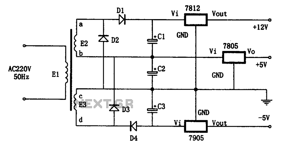
The circuit illustrated in the figure represents a specialized power supply configuration. It is straightforward in design and can be constructed using two identical secondary windings to generate three distinct DC voltage outputs: +5V, -5V, and +12V. The circuit...
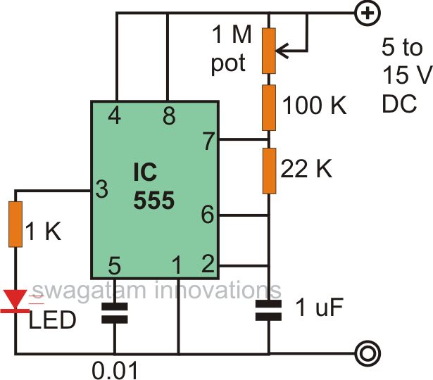
The astable multivibrator mode is the most basic operational mode of the IC 555. In this mode, it functions as a free-running oscillator. When the oscillator rate is sufficiently reduced, it can be used to drive LED lights. The...
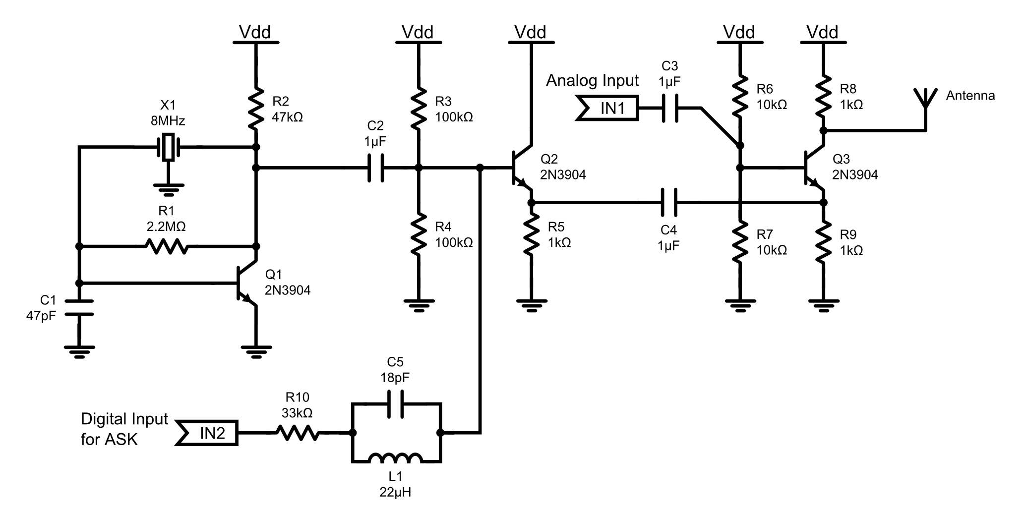
This is an 8MHz amplitude modulated (AM) radio transmitter designed primarily for practical applications and as an educational exercise in electronics. The objective was to create a simple radio transceiver that could be used in future projects requiring basic...