
Simple AC short circuit protection

The described circuit serves as a protective mechanism for electrical systems, specifically designed to monitor the load connected to an AC power supply. The relay (KA) acts as a switch that controls the connection between the power supply and the load (Rfz). Under normal operating conditions, the relay remains energized, allowing current to flow to the load.
In the event of a short circuit, which is characterized by a sudden drop in resistance, the voltage across the relay coil (KA) decreases sharply. This voltage drop triggers the relay to de-energize, effectively opening the circuit and disconnecting the load from the power supply. This rapid response is crucial for preventing damage to the load and reducing the risk of fire or other hazards associated with electrical faults.
The LED tube (VL) serves as a visual indicator of the short-circuit condition. When the relay releases due to the voltage drop, the LED is powered, illuminating to alert users of the fault condition. This feature enhances the safety and reliability of the system, allowing for immediate identification of issues that require attention.
Overall, this circuit design is essential for ensuring the protection of electrical loads in AC power applications, providing both automatic disconnection in fault conditions and visual feedback for maintenance and troubleshooting purposes.AC power supply voltage is normal, relay, connected to the load (Rfz) circuit. When the load short-circuit failure, KA voltage drop across quickly, KA release, cut off the load circuit. Meanwhile, the light emitting diode tube VL lights indicating the short circuit occurs.
Related Circuits
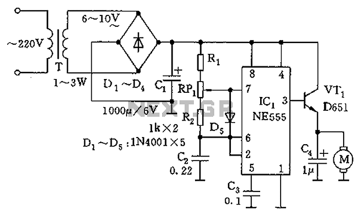
The circuit utilizes a 555 timer as the core component to create an astable multivibrator. The oscillation period T is given by the formula T = 0.693 (R1 + 2R2) C1, which corresponds to an oscillation frequency of approximately...
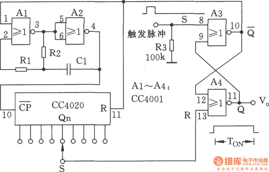
The NC monostable multivibrator circuit depicted in the chart consists of four 2-input NOR gates (CC4001) and a 14-bit binary serial counter/divider (CC4020). It is primarily utilized as a time delay switch or timer in automatic control equipment. The NC...
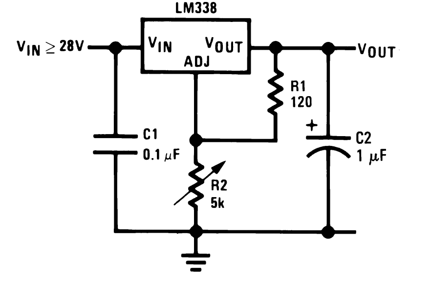
The LM338 integrated circuit (IC) from Texas Instruments is a versatile component that can be configured in various ways to create high-quality power supply circuits. The first circuit demonstrates the typical wiring format around the IC, providing an adjustable...
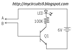
This circuit offers an advantage over traditional continuity testing devices, which typically utilize a multimeter to assess circuit continuity. Multimeters are not suitable for testing high impedance or resistance circuits, such as transformers, capacitors, and high-value resistors. This circuit...
This circuit is designed to indicate, via a flashing LED, when room noise exceeds a predetermined threshold. The thresholds are set at three fixed levels: 50 dB, 70 dB, and 85 dB. Two operational amplifiers (op-amps) are utilized to...
The loop can be any type of hookup wire, with a maximum resistance of about 90K. Using very thin wire (40AWG, for example) will create a highly sensitive trip wire, but will reduce the distance it can be strung...