
Room Noise Detector Circuit

The circuit comprises a miniature electret microphone that serves as the sound input device. The microphone converts sound waves into an electrical signal, which is then fed into the first op-amp configured as a non-inverting amplifier. This stage amplifies the weak audio signal to a suitable level for further processing. The gain of the op-amp can be adjusted depending on the desired sensitivity of the microphone.
Following the first op-amp, the signal is routed to a second op-amp, which further amplifies the signal and may also include a comparator function to determine if the amplified signal exceeds any of the predetermined thresholds. The output of the second op-amp is connected to a threshold detection circuit that utilizes resistors to set the reference voltages corresponding to the 50 dB, 70 dB, and 85 dB levels.
The circuit's operation is controlled by a switch (SW1), which allows the user to select the desired threshold level. In the first position, the circuit is powered off to conserve energy. In the second, third, and fourth positions, the circuit is powered on, and the sensitivity threshold is adjusted accordingly. When the noise level exceeds the selected threshold, the output of the second op-amp triggers a transistor or a similar switching device to activate the LED.
The LED serves as a visual indicator, flashing to signal that the ambient noise level has crossed the set threshold. The flashing behavior can be implemented using a simple timing circuit, which may consist of additional passive components such as resistors and capacitors to create a blinking effect. The current draw of the circuit is relatively low, at 1 mA when the LED is off, and increases to 12-15 mA when the LED is continuously lit, ensuring that the circuit remains efficient while providing clear visual feedback.This circuit is intended to signal, through a flashing LED, the exceeding of a fixed threshold in room noise, chosen from three fixed levels, namely 50, 70 & 85 dB. Two Op-amps provide the necessary circuit gain for sounds picked-up by a miniature electret microphone to drive a LED.
With SW1 in the first position the circuit is off. Second, third and fourth positions power the circuit and set the input sensitivity threshold to 85, 70 & 50 dB respectively. Current drawing is 1mA with LED off and 12-15mA when the LED is steady on.. 🔗 External reference
Related Circuits
Feedback in a public address amplifier should be avoided. The ideal solution is to adjust the positions of the microphone and speaker; however, this is not always feasible in many situations. A frequency shifter that alters the output frequency...
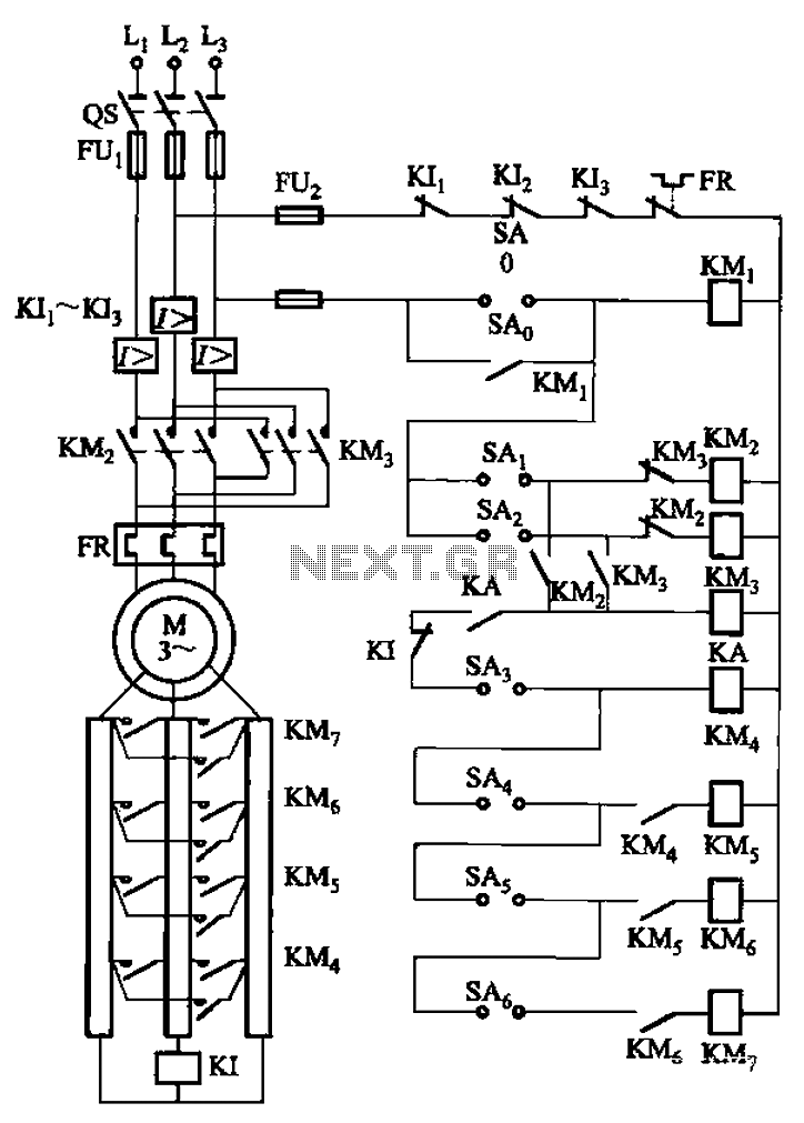
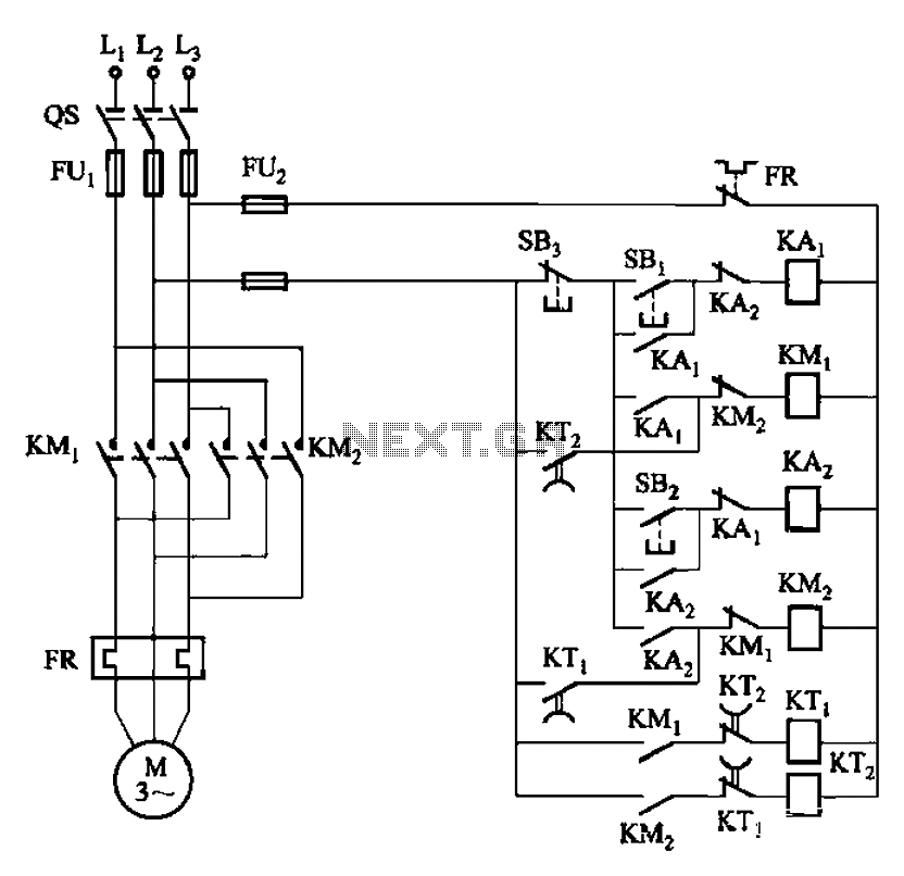
The circuit depicted in Figure 3-168 utilizes a controller for speed grading and reversing control. A reverse brake is connected to the rotor circuit through an overcurrent relay, labeled KI, for control. The current relay KIi to KI3 serves...
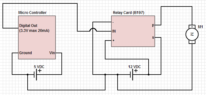
The objective is to control a 12 VDC device (on/off) from a microcontroller using a relay card. The relay requires a 12 VDC operating power supply. To achieve the control of a 12 VDC device using a microcontroller and a...
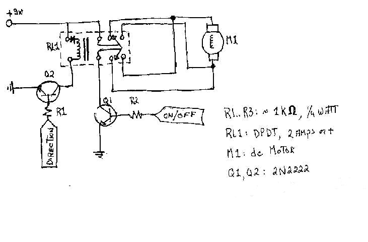
To create the circuitry described, a computer software capable of controlling a parallel port is required, with an estimated cost of approximately $30. For instance, a transistor (model number 2N2222) is priced around $0.50, while a DPDT relay costs...
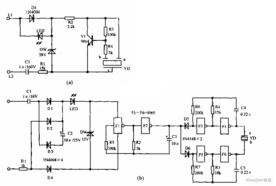
The telephone electronic ringer circuit is illustrated in the provided figure. It features an NPN transistor (either 9014 or 3DG12) as the primary component. The sound device, referred to as YD, functions as both a feedback device and is...
The circuit depicted in Figure 3-131 utilizes a relay instead of a speed control relay. It is designed to operate effectively in dusty environments and other challenging conditions. The circuit operates by employing a relay as a primary switching mechanism,...