
Self Powered Current Sensing

A current sensing circuit serves a crucial role in monitoring the flow of electric current in various applications, particularly in high-side configurations. Such configurations are advantageous because they allow for the measurement of current without interrupting the circuit, thus maintaining the integrity of the load and ensuring accurate readings.
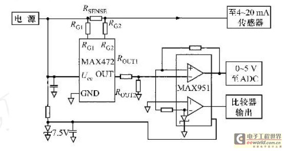
The high-side current sensing circuit typically consists of a shunt resistor placed between the load and the positive supply voltage. The voltage drop across this shunt resistor is proportional to the current flowing through it, following Ohm's Law (V = I * R). To accurately measure this voltage drop, an operational amplifier (op-amp) is often employed to amplify the small signal generated across the shunt resistor.
In a typical design, the op-amp is configured in a differential mode to reject common-mode voltage variations, which is essential in high-side applications where the supply voltage can be significantly higher than the ground reference. The output of the op-amp can then be fed into an analog-to-digital converter (ADC) for digital processing or directly utilized in a feedback loop for control applications.
To enhance the performance of the current sensing circuit, additional components such as filters may be included to minimize noise and improve stability. Moreover, proper selection of the shunt resistor value is critical; it must be low enough to minimize power loss while still providing a measurable voltage drop for accurate sensing.
In summary, the high-side current sensing circuit is an essential component in various electronic systems, providing reliable current measurements that are crucial for system monitoring, control, and protection.This is a current sensing circuit that senses the current at the high side (between load and positive supply). This circuit take advantage from.. 🔗 External reference
Related Circuits
In certain industries, a computer-controlled 4-20 mA current loop is utilized to manage various equipment. This current loop is employed to transmit a signal over a distance. The 4-20 mA current loop is a standard method for transmitting analog signals...
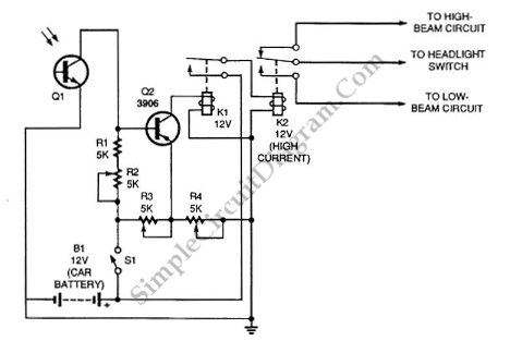
Automatic headlight dimmer circuit diagram for a car's headlight. This circuit ensures maximum brightness for optimal visibility while automatically switching when necessary. The automatic headlight dimmer circuit is designed to enhance driving safety by adjusting the brightness of the vehicle's...
This is a INA159 Dual-Polarity, Bidirectional Current-Shunt-Monitor Circuit. This circuit uses OPA340 because it has near rail-to-rail input and output swing. The INA159 is an integrated circuit designed for high precision current sensing applications. It is capable of measuring bidirectional...
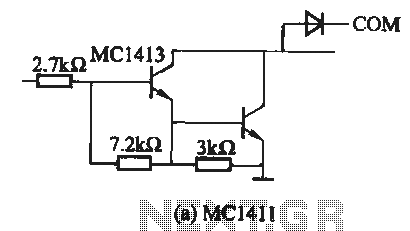
The MC1411 series is a Darlington driver with a compact, reliable internal structure. It is particularly suited for high-voltage applications, functioning effectively as a high-voltage peripheral driver. This driver can directly control relays, lights, and other loads. It is...
Field bus technology and intelligent instrument technology are currently two of the most rapidly evolving technologies in automation and control. In the realm of field bus technology, the CAN bus has established itself as a relatively fast communication standard...

This design concept addresses a major challenge associated with the use of photodiodes in high-speed applications such as barcode scanners, CD-ROMs, and DVDs, specifically the high output capacitance of the diode. The critical component in the circuit is the...