
Sense of Time tester circuit

The described circuit operates as an astable multivibrator, a configuration commonly used for generating square wave signals. In this setup, the timing of the LED's illumination is determined by the charge and discharge cycles of capacitor C1, which are regulated by resistors R1 and R2. When S2 is closed, the circuit enters its oscillation mode, causing the LED to flash at a defined interval. The time period of the oscillation can be calculated using the formula:
\[ T = 0.693 \times (R1 + 2R2) \times C1 \]
where T is the total period of the oscillation. The LED remains lit for approximately 0.1 seconds, which can be adjusted by varying the capacitance of C1 or the resistance values of R1 and R2.
Switch S1 serves a critical function in the circuit. When pressed during the LED's illumination period, S1 interrupts the discharge path of C1, effectively "freezing" the state of the circuit and keeping the LED lit beyond the initial 0.1 seconds. This feature allows for user interaction, enabling the operator to maintain the LED in an ON state if the timing is accurately judged.
To modify the flashing rate or duration of the LED, R1 and R2 can be adjusted to alter the charge and discharge times of C1. Increasing R1 or R2 will extend the ON time of the LED, while decreasing these resistances will shorten the duration. Similarly, changing the value of C1 will have a direct impact on the timing characteristics of the circuit.
This circuit can be utilized in various applications where visual alerts or indicators are required, especially in situations where user interaction is necessary to maintain the alert state. It is essential to consider the tolerances and ratings of the components used to ensure reliable operation within the intended application.When S2 is ON, the circuit here operates as an astable multi vibrator and the LED is lit for about o. 1sec, flasing every 1. 5 seconds. Since the human reaction time is more than this, you cannot catch it once it is seen o, by pressing S1.
If your sense of time interval is good, and you press S1 with in that 0. 1 sec, the discharging of C1 stops and then th e lamp stays lit. you may change the ON and OFF periods by changing R1 and R2 or C1 to suit your convenience. 🔗 External reference
Related Circuits
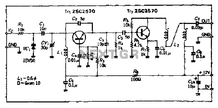
The Bong circuit is a high-frequency Colpitts oscillator that utilizes a Ge coil (L). It features two heads and is designed for simple production. The frequency of oscillation can be determined, and testing is conducted to ascertain the value...
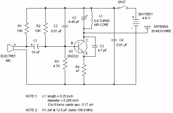
Wireless FM Transmitter. The site provides some explanation on how the circuit operates; however, there are uncertainties regarding certain components, including the electret microphone and the frequency modulation process. The electret microphone operates at a current of 200 µA,...
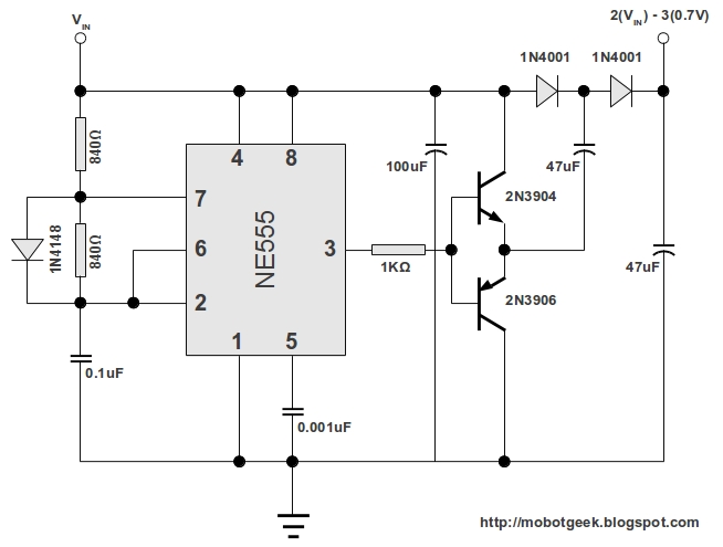
This DC voltage doubler circuit generates a voltage that is double its supply voltage. It is advantageous when a higher voltage level is required from a single lower voltage power supply. Due to the low current consumption in such...
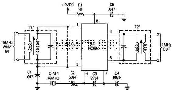
This simple frequency converter mixes the 15-MHz WWV/WVH signal with a 16-MHz signal from the local oscillator (LO) to convert it down to 1 MHz, enabling it to be received on an AM-band receiver. The frequency converter operates by utilizing...
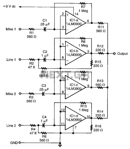
Designed around an LM3900 quad op amp, this mixer combines two line inputs and two microphone inputs, summing them at the output terminal. Resistors R7 through R10 can be adjusted to vary the gain, approximately +23 dB. The mixer circuit...
The external audio spectrum display circuit is designed for high-end audio equipment, providing both real-time playback signal analysis and visually appealing effects. This display does not require any electrical connections to the sound equipment; it can simply be placed...