
SEM/STEM detectors and CRTs

To modernize the system, it has been determined that the ASID panel, which controls the scanning of the electron beam during SEM/STEM imaging, contains an extra contact labeled SG6 on the back panel. Upon opening the back panel of the ASID unit, the signal generator card (SG) and the SG6 contact are accessible. According to the circuit diagram, activating the external scan mode requires connecting pin 5 of SG6 to ground. This mode bypasses the scan generator function of the ASID panel, allowing for the insertion of custom scan signals at pins 1 and 2 for horizontal and vertical scans. The signal level is ±10 Volts, which is compatible with the PXI-6229 card designated for this task.
To connect to SG6, a signal cable was assembled, linking SG6 internally to the front of the ASID. A switch was incorporated to connect pin 5 to ground, and horizontal and vertical scan signals were equipped with SMB panel connectors. A free slot on the ASID front panel was utilized for the switch and connectors. The detectors each have BNC connector outputs; the original cables were replaced with custom cables leading to the same DAQ card mentioned earlier. This electronic setup allows the ASID unit to manage signal conditioning between the DAQ card and the beam-scan coils, rendering the CRTs unnecessary. The only functions remaining on the ASID panel will be for stigmatism correction and detector contrast adjustment.
The LabView software is configured to generate two sawtooth signals for horizontal and vertical synchronization. This is set up as a single DAQ task to avoid hardware conflicts. During signal generation, detector data is collected in parallel, with the option to read data faster than it is written, thereby improving the signal-to-noise ratio. This feature is implemented as a user-selectable "scan speed" option in the program. Data is read at a rate of 200 kHz, and depending on the selected slower scan speed, more samples can be collected for each position on the sample.
Furthermore, there are two scanning options: scanning one horizontal line followed by data collection from the detector, or reading the entire image in one sampling. The former allows for handling larger image sizes beyond 512x512 pixels, as only one scan line needs to be buffered in the DAQ card at a time. The latter option is significantly faster. Both methods have been implemented, with the one-line scan mode reserved for final imaging and the whole-image scan mode utilized for rapid previews, achieving nearly 2 frames per second at a resolution of 128x128 pixels.
The SEM imaging mode has demonstrated a resolution of approximately 50 nm, with expectations for improvement upon further optimization of the system. The green color displayed in the images is a nod to the nostalgia for the green CRT monitor. Additionally, due to the in-situ probing capabilities of the setup, it is possible to measure the impact beam current of the sample during the SEM scan, enabling mapping of this data, which will be reported in future communications.The TEM that we have, the Jeol 2000fx is equipped with two extra detectors, one secondary electron detector, i. e. SEM imaging, as well as a STEM detector at the bottom of the microscope. Because the system are from the 80`s the imaging from these detectors is (read "was")accomplishedby using photographic film to copy the image shown on the CRT.
An extra CRT monitorspecificallyused for this task is located in a free standing box in which the camera with light sensitiv polaroid film is attached to. Nowadays, everything is digital, and polaroid imaging is therefore not very user friendly or timesaving.
Besides, one of the two CRT`s used for setting upp the image to be captured is broke in our system and the other one is almost burned out. -Time to move into the nextcenturyof technology. By different means I found out that the ASID panel, i. e the one thatcontrolsthe scanning of the electron beam during SEM/STEM imaging, has a extra contact hidden behind the backpanel, labeled SG6, figure 1.
Figure 1, After opening the back-panel of the ASID unit the signal generator card (SG) is somewhat exposed as well as the extra contact SG6, used for external scan control. If one looks at thecircuitdiagram, figure 2, one can se that the external scan mode is activated by connecting pin 5 of the SG6 to ground.
This mode bypass the scan generator function of the ASID panel and allows you to insert your own scan signals at pin 1 and 2 for horisontal and vertical. The signal level happens to be ±10 Volts and this is lucky thus the PXI-6229 card that I use for this task also has this amplitude range limit.
To connect to the SG6 I assembled a signal cable from SG6 internally to the front of the ASID, a switch was used to connect pin 5 to ground, and the horisontal and vertical scan signals got two SMB panel connectors, se figure 3. figure 3 There was one free slot on the ASID front-panel that I used for the switch and connectors. (left) the backside of the ready made front-panel and the frontside of it (right). The detectors each have BNC connector output I just simply detached the regular cables to these ones and connected my own that leads to the same DAQ-card as mentioned above.
This electronic setup will results in that the ASID unit will just handle signal conditioning between my DAQ-card and the beam-scan coils, the two (three) CRT`s will no longer be needed. The only buttons on the ASID panel in use will be stigmatism correction and detector contrast setting.
What you want to do is to get LabView to generate two signals, two sawtooth for horisontal and vertical synch signals. I configured this as a single DAQ-task where both are written at the same time to avoid conflicts on the hardware.
During signal generation you also need to collect the detector data, this I configured as a parallel task to one the above. You have one options here and that`s to read data faster than you write, this willimprovesignal noise ratio for you and I made this option as a user "scan speed" selection in the program.
I always read data as fast as possible, 200kHz, and depending on what slower scan speed setting one choose, more samples are read for each position on the sample. You also have anotheroption here and that is to scan one horisontal line then collect the data from the detector or to read the hole image in one sampling.
The former gives you ability to handle bigger image sizes, i. e. beyond512x512 pixels images, because you only need to have one scan line in the DAQ-card buffer each time. The later alternative isof-coursemuch faster. I choose to implement booth, the one-line scan mode for final imaging and the hole-image scan mode for fast preview as this gives you almost 2 frames/s in 128x128 pixels.
Figure 5, SEM image of the same sample and region as shown in figure 4, but at slightly lower magnification this time. Resolution is in this quick check seems to be around 50 nm for the SEM imaging mode, but Iexpectthis to improve if one tveek the system to more optimal settings.
(the green color is for those of us who misses the green CRT monitor. ) Due to the in-situ probing that we usually do in our setup we canmeasurethe impact beam current of the sample during SEM scan and make mapping of this as well this is yet to be done and I report on this later. 🔗 External reference
Related Circuits
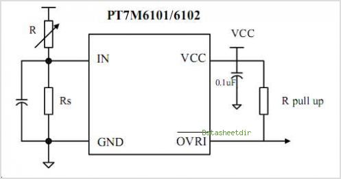
The PTB78560x is a series of 30 W rated isolated DC/DC converters designed to operate from a standard 24 V or 48 V telecom central office (CO) supply. Housed in a 12 package, each model features a wide adjustable...
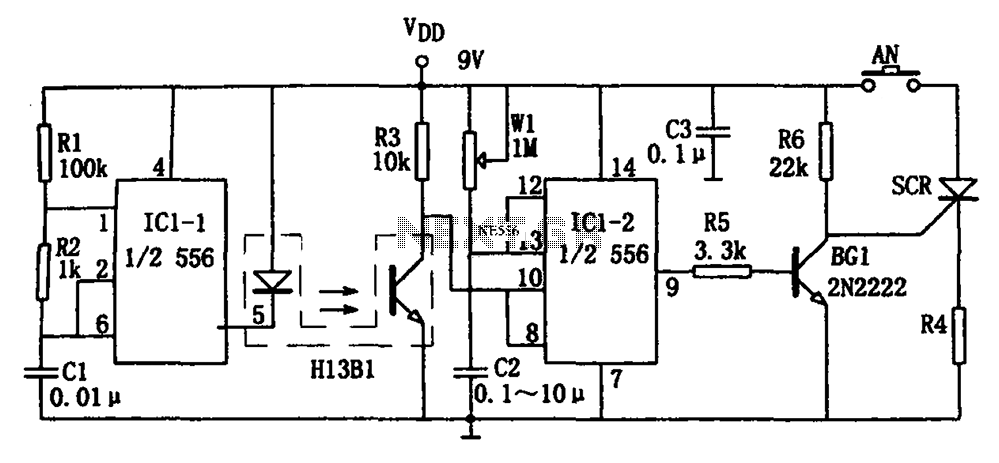
The circuit shown is a photoelectron pulse missing detection circuit. It includes an optoelectronic slotted switch H13B1, a dual time base circuit using a 556 timer IC, and several RC components that form a one-shot multivibrator. The design incorporates...
A bright lamp flashes in synchrony with the lightning bolts, indicating the proximity and intensity of the storm. The described circuit operates as a storm warning system, utilizing a bright lamp to provide visual alerts in response to lightning activity....
Motion detectors commonly utilize ultrasonic sensors due to their sensitivity and rapid response. However, a significant drawback of these sensors is their tendency to react to environmental vibrations, such as sounds from passing cars or planes, leading to unexpected...
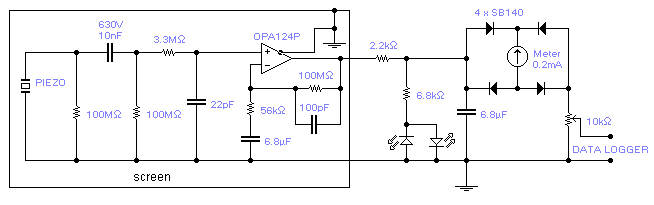
The piezoelectric element of a kitchen gas lighter is utilized in this simple yet effective seismic detector. The piezo element must be positioned vertically, with one end firmly grounded. A loose package containing 2-3 pounds of fine gravel should...
This circuit utilizes a 1458 dual operational amplifier (op-amp) to create a radar detector. Capacitor C1 serves as the radar signal detector. The first op-amp functions as a current-to-voltage converter, while the second op-amp buffers the output to drive...