
Fully automatic watering circuit for flower pots
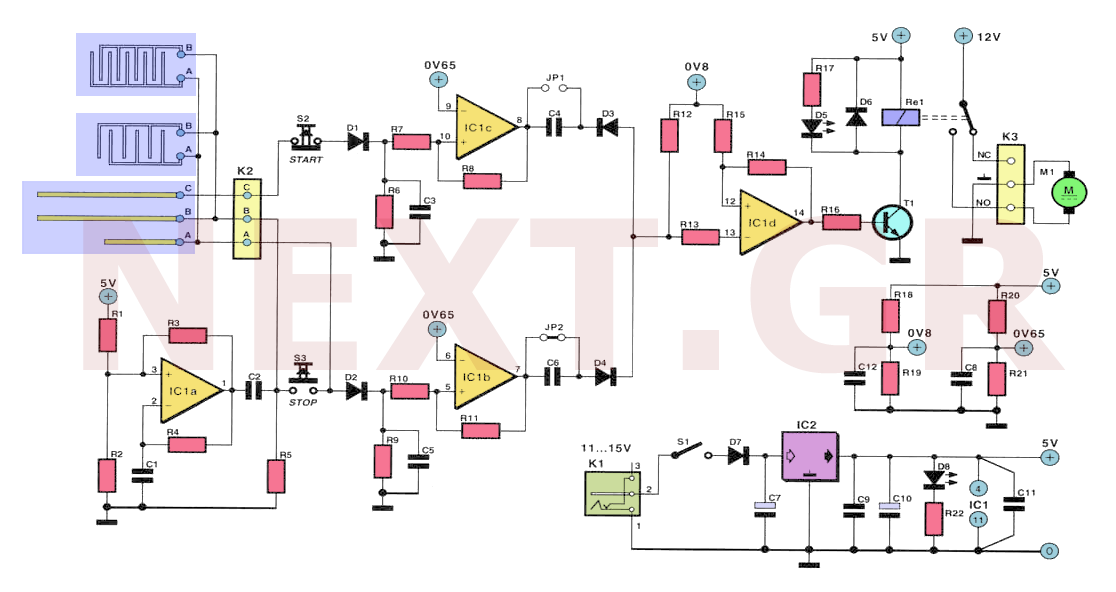
This "automatic watering" system incorporates two moisture meters placed at the top and bottom of the pot. These meters signal when the two most extreme conditions—adequate water and insufficient water—are detected, prompting appropriate actions for each scenario. These actions involve activating or deactivating an electric water pump that transfers water from a reservoir to the pot. An additional overflow sensor at the top of the pot ensures safety by preventing overflow, even if the upper sensor fails. If the water level drops to the bottom of the pot, the sensor located there alerts a central control unit to activate the water pump. Once the water level reaches the upper sensor, the control unit stops the pump, indicating that the pot has sufficient water. The device can also be operated manually via switches, and it can be configured with an auxiliary relay for controlling a drill pump or a solenoid valve.
The sensors consist of two copper conductors mounted on a single board, insulated from each other. It is advisable for the conductors to have branches to cover a larger surface area. The resistance measured between the conductors is influenced by the presence of water due to its high conductivity. The driving assembly includes electronic circuits that respond to variations in resistance, generating the necessary signals to control the pump.
One of the sensor contacts connects to the output of an oscillator. The presence of water around the sensor increases the signal level transmitted to the second contact. The sensor and resistor form a voltage divider, where the voltage at the divider node increases significantly when surrounded by water. When the overflow sensor indicates sufficient water, a substantial current flows from the oscillator to the rest of the device, causing the pump to stop. Although the device could theoretically operate with a constant voltage supplied to the sensors, this is impractical due to the electrolysis phenomenon that would degrade the electrodes.
The schematic features a rectangular oscillator identified as IC1a. The oscillator signal is transmitted through connection B to the water in the pot. In the absence of water, the oscillator signal does not reach connections A or C. Diodes D1 and D3 smooth the alternating voltage. When the sensor is dry, capacitor C3 stops accepting a new charge via D1, leading to discharge through resistor R6. This results in the output of comparator IC1c dropping to zero. The voltage drop is transformed by C4 and D3 into a brief negative pulse, which is fed to the input of comparator IC1d, causing its output to switch to "1," activating transistor T1 and the pump relay. Resistor R14 introduces the necessary delay for comparator IC1d.
As the pump operates, indicated by LED D5, the water level in the tank rises. When the resistance between connections B and C decreases, capacitor C3 begins to recharge via D1. Once C3 reaches a predetermined voltage, the output of IC1c changes to "1." However, due to the pulse through D3, this does not affect the state of comparator IC1d, keeping the pump operational. If the water level rises sufficiently that electrode B connects to contact C as well as A, it indicates adequate water in the container. In this case, electrode A sends a current through capacitor D2 to capacitor C5.
Comparator IC1b functions similarly to IC1c, with the distinction that diode D4 is reverse-polarized relative to D3. Consequently, when comparator IC1b changes state, a positive pulse occurs, causing the output of IC1d to revert to its original state. This stops T1 and deactivates the pump relay, turning off LED D5. The device can also be manually controlled without the sensors using switches S2 and S3.
Bridges JP1 and JP2 allow selection of priority between the signal that activates or deactivates the pump. If JP2 is connected and JP1 is not, a "1" at the output of IC1b ensures that D4 remains continuously on (assuming sensor A is wet). This maintains the state of IC1d regardless of short negative pulses at D3, ensuring that the pump activation signal takes precedence.
The circuit board includes electronic components and five sensors, which must be separated before component installation. The larger sensor includes moisture electrodes A, B, and C, while the smaller sensors provide additional overflow protection. The placement of components on the board is straightforward. The indicator light D5 is linked to the digital switch S2. To operate automatically, JP2 must be installed on the board, with JP1 unused. Prior to commissioning, the copper paths of the sensors should be tinned to prevent corrosion.
The device, along with the pump, requires a power supply capable of handling the pump's operating current. It is advisable to ensure that the sensor connection cables are durable. A preliminary test before normal operation is recommended, verifying that the pump stops automatically when water covers sensor A. If it does not, switch S3 can be used as an emergency shutoff, prompting a check of sensor connections for any issues.
The additional sensors can be installed at the top of the pot for overflow control or at various points along the feed pipe to monitor for leaks. These safety electrodes connect in parallel to connections K2. If the pot is smaller than the larger electrode, smaller sensors should be utilized. If bridge JP1 is installed, it ensures that accidental noise from a pulse at the inlet A does not cause the pump to stop, which may be beneficial for draining large containers. However, both bridges should never be used simultaneously.
Components include various resistors, capacitors, semiconductors, and other necessary elements for the circuit's operation. Resistors range from 1kΩ to 1MΩ, capacitors from 2nF to 100µF, and semiconductors include diodes and transistors suitable for the circuit's requirements.Many times for various reasons we forget or can not water the plants that we have in our homes. And many humidity sensors units just notify us with a beeping sound or with a flashing light, that the pot needs watering. But what if we are away from home? This circuit comes as a solution to this problem. Depending on humidity of the pot at different levels, this device can decide when the plant need water as well as how much water should be added each time and does the job for us.
Without using a micro controller, rather regular chips, this circuit will solve your watering problems of your favorite pots for ever.
This "automatic watering" is used in conjunction with two moisture meters, placed at the bottom and at the top of the pot. These meters alert us to the fact that the two most extreme situations, namely adequate water and too little water, have emerged and that we have to take the appropriate measures for each one.
These measures consist of activating or shutting down an electric water pump that brings water from an auxiliary pot to the pot. An additional overflow sensor at the top of the pot keeps us safe so that if for some reason the upper sensor does not work, there is no overflow of water.
If the water level drops to the bottom of the pot, the sensor mounted there notifies a central control unit that turns on the water pump. When the water level reaches the second sensor, the control plant undertakes to stop the pump, since the pot already has enough water.
The device can also be driven manually by means of switches, likewise it can be used with an auxiliary relay for the operation of a drill pump or a solenoid valve.

The Sensors
As sensors two copper conductors are placed on one piece of board, which are separated and insulated from each other. It would be advisable for the ducts to have branches, to cover a larger surface. The resistance we can measure between pipes is influenced by the existence of water or not, due to the high conductivity of the latter.
The drive assembly contains electronic circuits which react to variations of this resistance and produce the signals required to drive the pump.

One of the two contacts of the sensor is connected to the output of an oscillator. The more fluid the environment around the sensor is, the higher the signal level of the oscillator is transmitted to the second contact.
The sensor and resistor R form a voltage divider. The voltage at the splitter node is significantly higher if the sensor is surrounded by water. When the overflow sensor or the indicator that sufficient water passes into a conductive state, a corresponding large current will flow from the oscillator to the rest of the device and cause the pump to stop. In theory, the device could work even if we fed the sensors with a constant voltage, but in practice this is not done because the electrolysis phenomenon that would be present would render the electrodes useless.
The Schematic
The rectangular oscillator we mentioned earlier is IC1a.
Through connection B the oscillator signal is transferred to the potting water. This duct is down in the pot.
If there is no water in the tank, the oscillator signal does not reach either the connection A or the connection C. The D1 and the C3 are intended to smooth the alternating voltage. When the sensor is dry C3 ceases to accept a new load through of D1, resulting in discharge through the R6.
This results in the output of the IC1c comparator going to zero. This voltage drop is converted by C4 and D3 into a short negative pulse, which ends at the input of the IC1d comparator. This pulse leads the output of IC1d to "1", transistor T1 in conductivity and pump relay on actuation.
Resistance R14 gives the required lag to IC1d comparator.
The pump starts to work (as shown by D5) and the water level in the tank rises. When the resistance between connections B and C becomes low, C3 starts to re-charge and D1. When the voltage of capacitor C3 reaches a certain value, the output IC1c output value again changes to "1".
This, however, thanks to the D3 passage has no effect on the IC1d comparator and so the pump still remains in operation. However, if the water level rises so much that the electrode B is not only connected to contact C but also to A, then there is enough water in the container.
In this case, electrode A flows through capacitor D2 through a current to capacitor C5.
Comparator IC1b has analogous function to IC1c. with the difference that the D4 diode has a reverse polarization relative to D3. For this reason, when we have a change in the condition of comparator IC1b, a positive pulse occurs that causes the output of IC1d to return to its original state.
T1 stops running and the relay stops feeding the pump (D5 stops shining). The device can also be controlled manually without the sensors, with the help of switches S2 and S3.
The Bridges
By using the two bridges JP1 and JP2 we can determine whether we want to give priority to the signal that is triggering or to the one that stops the pump. If JP2 is mounted and JP1 is not, then the value "1" at the output of IC1b ensures that D4 will go on continuously (assuming sensor A is wet).
Regardless of whether there are short negative pulses in the rise of D3, IC1d remains in the same steady state. The IC1b signal interrupting the pump always has priority.
The following example shows how important this feature is, if for some reason the cable connection to sensor C is interrupted.
C3 will be discharged even if the tank is full up with water (if the sensor A is wet). At the input of IC1d there is a pulse. If the JP2 bridle is not installed, the pump remains constantly in operation due to its pulse and even for as long as it is needed until the IC1d receives through the C6 a stop pulse. But this pulse is not going to occur, since the sensor A is already in the water. JP2 ensures that after stopping the pump at the input of IC1d, a continuous voltage is displayed, so that we never go into overflow situations.
Construction of the Circuit
The board shown in next figure includes, in addition to the electronic components and five sensors, which must be separated before fitting the components from the board equipment.

The large sensor you see includes the moisture electrodes A, B and C.
The other two are smaller and placed as extra protection against possible overflow. Placing the components on the board does not cause any particular difficulty. The D5 indicator light is on the digital switch S2. If you do not want to work manually, you need to place JP2 on the board. We do not use JP1. Before the device is commissioned, the copper paths of the sensors must be tinned to protect them from corrosion.
The device together with the pump is powered by a power supply, which can cover the relatively high pump operating current. Try the sensor connection cable to be as durable as possible. A small test before starting normal operation would not hurt. Put the water in the pot until the sensor A is covered. If this does not automatically stop the pump, turn S3 as an emergency switch. In this case, check if all the sensors are connected correctly and there is a cut cord.
The two excess sensors can be placed either at the top of the pot (for overflow control) or at a random point in the feed pipe to control possible leakage.
This security electrodes are connected in parallel to the K2 connections. If the pot is smaller than the large electrode. then we have to use smaller ones. If we put the JP1 bridging in the set, then we are sure that accidental noise due to a pulse at the pump inlet A will not cause the pump to stop. We take this opportunity when we want to empty very large containers. Never, however, have to place both bridges at the same time.
Components
Resistors
R1, R2, R12, R15 = 100k
R3, R4, R8, R11 = 470k
R5, R13, R16, R19, R21 = 1k
R6, R9 = 47k
R7, R10 = 10k
R14 = 1M
R17 = 330Ω
R18 = 5k6
R20 = 6k8
R22 = 390k
Capacitors
C1 = 2n2
C2, C3, C5, C8, C9, C11, C12 = 100n
C4, C6 = 220n
C7, C10 = 100μ / 16V
Semiconductors
D1-D4 = BAT85
D5 = LED 3mm red
D6, D7 = 1N4001
D8 = LED 3mm green
T1 = BC547
IC1 = TLC274
IC2 = 7805
Other
JP1, JP2 = bridges
K1 = slot for editing the board
K2, K3 = triplicate RM5 terminals
S1 = single-pole pushbutton
S2 = digital switch with working contact, large shape
Re1 = single-contact 6V relay
Water pump 12V or electric valve, etc
Related Circuits
Fast charging circuit that illustrates voltage and current waveforms along with the configuration of the fast charge circuit for the charger. The detection and control circuit consists of three inverters (GMOS) from integrated circuits, enabling automatic control functions. The fast...
Measuring inductance is important for creating hand-made inductors, particularly when engaging in do-it-yourself (DIY) coil winding. An inductance meter adapter can facilitate this process. An inductance meter adapter is a vital tool for accurately measuring the inductance of coils and...
This document details a 2W audio power amplifier circuit that utilizes a 14-pin LM380 package as the amplification element. The input signal is managed by a volume control potentiometer (Rp) rated at 20k ohms, with a coupling capacitance of...
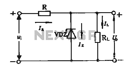
The simple voltage regulator circuit consists of a silicon regulator and a resistor. It is designed to rectify and filter DC voltage, as illustrated in the accompanying figure. The voltage regulator is connected in parallel with the load, and...
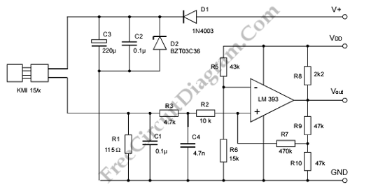
A modulated current is supplied by the integrated rotational speed sensor KMI 15/x. This current signal needs to be converted into a ground-referenced voltage signal. The KMI 15/x sensor operates by generating a modulated current proportional to the rotational speed of...
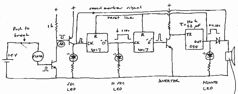
This box is a portable transfer standard to maintain and carry with you a local time signal of 59 short beeps (pips) plus a long 0.4 sec beeeeep on the full minute. At the start of the job, the...