
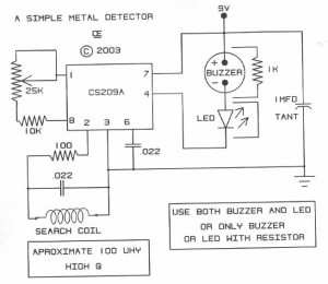
Metal detector with 555
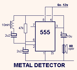
The circuit operates on the principle of inductance variation in response to the presence of a magnetic field. The core component is a 10mH choke, which is an inductor designed to resist changes in current. When a magnet approaches the choke, the magnetic field interacts with the inductor, resulting in a change in inductance. This change affects the resonant frequency of the circuit, which can be detected and measured.
The circuit typically includes a signal generator, which produces an oscillating signal at the resonant frequency of the inductor. The output from the inductor is fed into a frequency detection circuit, which could be implemented using a microcontroller or a dedicated frequency counter. The detection circuit monitors the frequency of the output signal and triggers an alert or activates a response mechanism when a significant deviation from the baseline frequency is detected.
To enhance sensitivity and reduce false positives, additional components such as capacitors may be included to form a resonant LC circuit with the inductor. The values of these components can be adjusted to fine-tune the circuit's response to specific magnetic fields or metal types. A comparator circuit may also be integrated to provide a clear digital output based on the detected frequency change, allowing for easy interfacing with other electronic systems or alarms.
This type of metal and magnet detection circuit can be utilized in various applications, including security systems, industrial automation, and proximity sensing in consumer electronics.This circuit detects metal and also magnets. When a magnet is brought close to the 10mH choke, the output frequency changes. 🔗 External reference
Related Circuits
This circuit serves as an alternative to the infrared beam break detector discussed in the June 2009 issue of Silicon Chip. It aims to provide a more efficient solution for detecting interruptions in an infrared beam. This alternative infrared beam...
Figure 2-33 (a) illustrates the schematic diagram of a robot approaching an object. When no objects are detected in front of the robot, it moves forward in a straight line. If an object is detected on the left or...
The metal detector circuit is presented here, illustrating a simple yet effective design. It utilizes a 40, 106 Hex Schmitt inverter IC, a capacitor, a search coil, and batteries. An advantage of connecting IC1b Pin 4 to a medium-wave...

This circuit illustrates a Wiper Speed Control Circuit Diagram. The sweeping rate of the wiper can vary from once per second to once every ten seconds. The Wiper Speed Control Circuit is designed to regulate the speed of windshield wipers...
The diagram illustrates a simple and efficient receiver designed for activating garage doors, starter motors, alarms, warning systems, and various other applications. The SCR utilized in this circuit features an extremely low trigger current of 30 µA, requiring only...
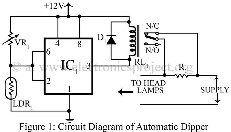
An automatic dipper for vehicles utilizing a timer IC NE555 and a light-dependent resistor (LDR) to control the headlight intensity of vehicles. This circuit diagram serves as a reference for various automobile projects. The automatic dipper circuit employs the NE555...