
Simple Metal Detector

Component List:
- R1 = 10K
- C1 = 100 µF/10V
- C2 = 10 nF
- C3 = 4-40 pF trimmer capacitor
- C4 = 4.7 pF
- IC1 = LM3909
- Q1 = 2N3904 NPN transistor
- LED1 = Red LED or any preferred color
This design represents a high-quality FM transmitter suitable for stereo systems or other amplifiers, capable of delivering a strong signal up to a distance of 500 meters with a power output of approximately 200 mW. The circuit operates on a 9V battery, with the audio frequency modulation stage closely associated with the BF494 transistor (T1).
Furthermore, the schematic details a stereo tube amplifier circuit utilizing 6SQ7-GT and 6V6-GT vacuum tubes. This tube amplifier configuration incorporates a total of five power vacuum tubes, inspired by the output section design of a typical late 1940s AM Trutone radio, producing an output of 4 Watts per channel (2x4W).
Additionally, a cell phone shield circuit is presented, which functions as a mobile charger while providing protection against unauthorized use or theft. This circuit is designed to emit a loud chirping sound if an attempt is made to remove the mobile handset.
Lastly, a 1.5 Watt FM transmitter circuit is described, which can cover a range of 1-2 kilometers. The component list for this circuit includes:
- R1 = 220K
- R2 = 4.7K
- R3, R4 = 10K
- R5 = 100 ohm
- C1, C2 = 4.7 µF Electrolytic
- C3, C4 = 1 nF
- C5 = 2-15 pF
- C6 = 3.3 pF
- Q1 = BC547C
- Q2 = 2N2219A
- P1 = 25K (acting as a condenser microphone volume control)
- MIC = Electret Condenser Type
For FM transmission, a small coil is recommended, constructed from thin gauge enamel magnet wire.Above diagram is a very easy and efficient receiver for actuating garage doors, starter motors, alarms, warning systems and many some other possibilities. The SCR, which has a extremely low trigger current of 30 uA is typical - it demands an input electricity of just 30 uW to activate the relay.
A high Q tuned. Easy FM tracking transmitter proje ct :). The circuit designed by Tony van Roon, and here the FM tracking transmitter diagram: Components List: R1 = 10K C1 = 100uF/10V C2 = 10nF C3 = 4-40pF trimmer capacitor C4 = 4. 7pF IC1 = LM3909 Q1 = 2N3904 NPN transistor LED1 = Red LED/or another color as you. This the Good Quality FM transmitter for your stereo or any other amplifier gives you a pretty good signal strength up to a range of 500 metres having a power output of about 200 mW.
This circuit can be operated with a 9V battery. The audio-frequency modulation stage is constructed close to transistor BF494 (T1), . This is the circuit diagram of stereo tube amplifier using 6SQ7-GT and 6V6-GT. The tube amplifier circuit is uses the total of 5 power vacuum tube. The diagram is based on the output section design of typical late 1940`s old AM Trutone radio with 6 tubes. The output will be 4 Watts per channel (2x4W. This is the cell phone shield circuit which can be used as mobile charger. Give protection to your cell phone from unexpected use or theft working with this easy circuit. It is able to produce a loud chirping sound when someone tries to take away the mobile handset. The added function is that the circuit. This is 1. 5 Watt FM Transmitter circuit. This circuit should be able to cover 1-2 KM range. Components List R1=220K R2=4. 7K R3, R4=10K R5=100ohm C1, C2=4. 7uF Electrolytic C3, C4=1nF C5=2-15pF C6=3. 3pF Q1=BC547C Q2=2N2219A P1=25K MIC=Electret Condenser Type P1 act as condenser microphone volume level.
For FM, coil will be small. Use thin gauge enamel magnet wire. the diameter. 🔗 External reference
Related Circuits
An AM modulator for the medium wave (MW) band enables playback of music from a CD or MP3 player on compatible radios during the daytime. This device is not classified as a transmitter due to its low output power...
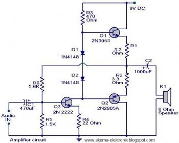
The initial section of the circuit is a preamplifier that utilizes transistor Q1 (2N2222). The collector of transistor Q3 is connected to the base of transistor Q2 (2N2905A), which creates a complementary symmetry pair with Q3 (2N3053). The amplified...
S1 is a power switch. U2 drives counter U3 by producing a pulse when S2 is depressed. U4 and DISP1 read the count of counter IC U3. S3 is a reset to zero switch. The counter is a basic...
This circuit can be constructed using readily available, low-cost components, some of which may even be found in a junk box. The specified value of 22 for resistor R1 results in an average current of approximately 65 mA flowing...
This circuit provides a straightforward method for measuring the voltage of a low-impedance voltage source. It operates as follows: P1, a 1-W potentiometer, acts as a voltage divider in conjunction with resistor R1. The voltage at their junction is...
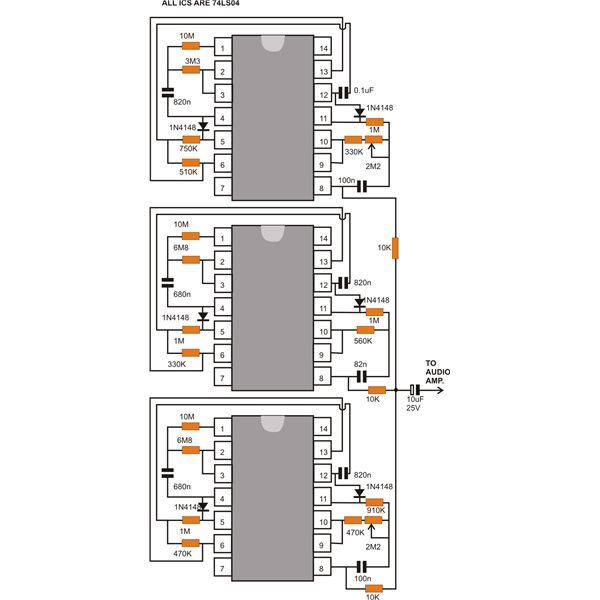
This document discusses a compact machine gun sound effect generator circuit. Once constructed, it can be integrated with any audio amplifier to create a realistic war-like simulation. This small hobby project is suitable for all electronics enthusiasts and generates...