
Three-phase switch
The described circuit involves a three-phase switching system designed for low-voltage applications. The schematic substitution mentioned is aimed at enhancing clarity and understanding of the operational principles behind the circuit. The triac driver serves as a key component in this setup; however, it is important to recognize its limitations when dealing with 3-phase voltage levels, as it may not perform optimally under such conditions.
In this context, three-phase switches are employed to manage the flow of electrical power across three separate phases, which is a common requirement in industrial and commercial power distribution systems. The use of low-voltage switching enhances safety and efficiency in managing electrical loads.
For applications requiring higher current handling, the circuit can be modified to incorporate inverse parallel silicon-controlled rectifiers (SCRs). These SCRs can be triggered in a manner that allows for greater control over the power delivered to the load. The inverse parallel configuration allows for bidirectional current flow, which is essential for AC applications. Each SCR is triggered at specific intervals to maintain the desired phase control and ensure optimal performance of the circuit.
The overall design of the circuit should include appropriate protection mechanisms, such as fuses or circuit breakers, to safeguard against overcurrent conditions. Additionally, proper heat dissipation measures must be considered, especially when utilizing SCRs, as they can generate significant heat during operation. The layout should also ensure minimal electromagnetic interference (EMI) and incorporate adequate filtering to maintain signal integrity across the switching components.
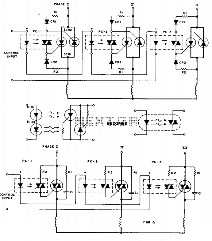
In conclusion, the schematic serves as a foundational tool for understanding the operation of three-phase low-voltage switches, while also providing pathways for scaling up to higher current capabilities through the integration of SCRs. Proper implementation of these components will result in an efficient and reliable three-phase power management system. To simplify the following schematics and facilitate easy understanding of the principles involved, the following schematic substitution is used (Note the triac driver is of limited use at 3 f voltage levels). The following are three-phase switches for low voltage. Higher currents can be obtained by using inverse parallel SCRs which would be triggered as shown. 🔗 External reference
Related Circuits
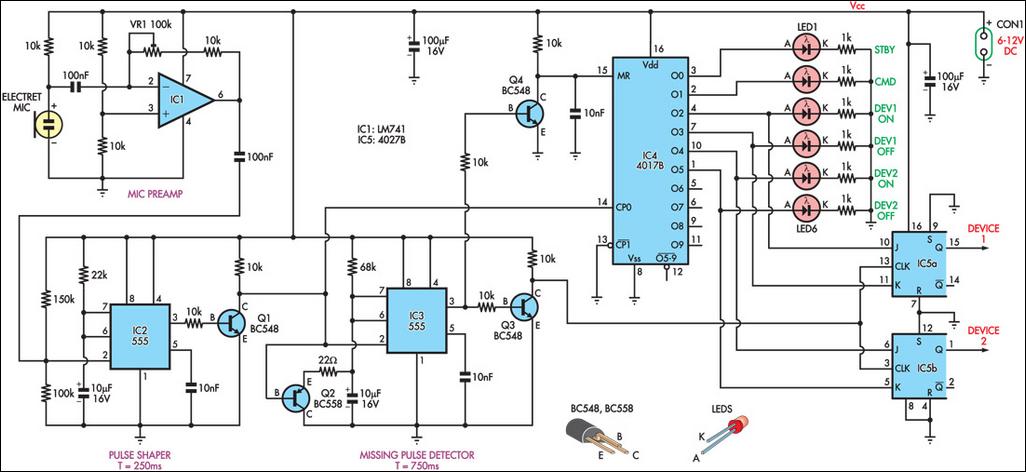
This circuit can switch two or more devices on and off in response to a series of rapid handclaps. The claps are detected by an electret microphone and amplified by a 741 operational amplifier (IC1). IC1 is configured as...
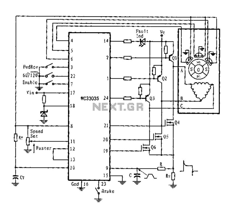
The application circuit is a three-phase full-wave six-step driving circuit for an open-loop motor controller. It features a power switching transistor of the Darlington type, specifically PNP, while the lower power switching transistors are N-channel power MOSFETs. Each device...
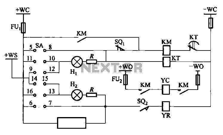
The DW10M de-excitation type switch is based on the DW10 automatic air circuit breaker, transitioning from normally open to normally closed contact. The models available include DW10M-200, DW10M-400, and DW10M-600. The control circuit for this type switch is illustrated...
A relay (RL1) is activated with a 100-second delay when a +12V power supply is connected to the circuit. Figure 2 illustrates a relay timer circuit utilizing a 555 timer, featuring two time ranges: 6-60 seconds and 1-10 minutes...
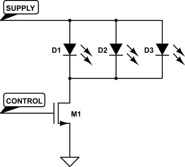
A Common Cathode LED strip is being utilized instead of a Common Anode variant, leading to the development of a modified circuit. The experience with FETs was limited, resulting in challenges as a minimum voltage equal to Vcc is...
The game was originally designed to position three balls locked in holes on a slowly rotating ring around the Deadworld. Once the third ball was secured, a mechanical arm would release them, dropping the balls onto the playfield. This...