
Missing pulse detector

In this electronic circuit configuration, the timing cycle is primarily governed by a pulse train input, which serves to reset the timing mechanism continuously. The circuit is designed to detect variations in the frequency of the incoming pulse train or identify instances where a pulse is absent. When such a change occurs, the timing cycle is allowed to complete, leading to a corresponding alteration in the output level.
To ensure reliable operation, particularly in environments where pulse trains may exhibit slight variations in timing, the time delay within the circuit must be calibrated to exceed the typical interval between incoming pulses. This adjustment guarantees that the timing cycle can effectively respond to the intended changes without being prematurely reset by the next pulse in the sequence.
The accompanying waveform graph illustrates the actual signal behavior during this operational mode, providing a visual representation of how the timing cycle interacts with the pulse train input. The graph typically includes features such as the pulse width, frequency, and the resulting output level shifts, which are critical for analyzing the performance and reliability of the timing circuit.
Overall, the design emphasizes the importance of precise timing adjustments and the ability to handle variations in input signals, making it suitable for applications where timing accuracy is paramount.The timing cycle is continuously reset by the input pulse train. A change in frequency, or a missing pulse, allows completion of the timing cycle which causes a change in the output level. For this application, the time delay should be set to be slightly longer than the normal time between pulses
The graph shows the actual waveforms seen in this mode of operation.
Related Circuits
One of the simplest methods of metal detecting is through a beat frequency oscillator. The circuit consists of two balanced oscillators: one provides a reference signal, while the other acts as the detector element. The frequency of the reference...
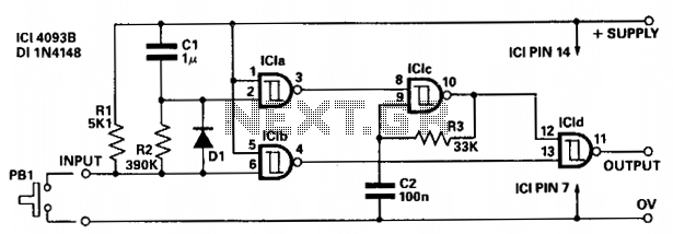
The circuit provides independent control of the initial delay and pulse rate. ICIc functions as a pulse generator, with its operation inhibited by the normally low output of ICla. When the circuit input transitions to low (e.g., when pressing...
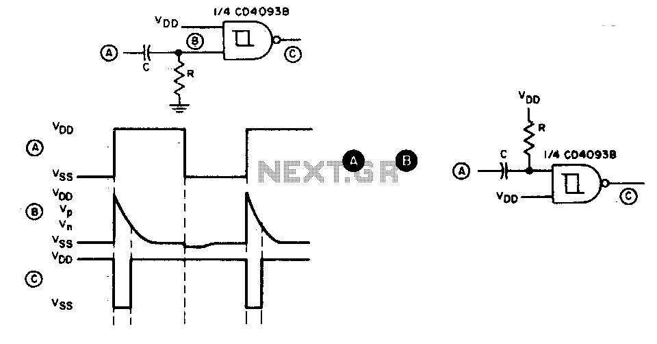
This circuit generates a brief negative-going output pulse in response to each positive-going edge at the input. The input signal is coupled to the circuit through a capacitor (C), and the duration of the output pulse is determined by...
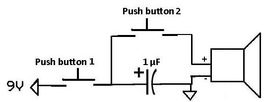
This project demonstrates how a capacitor can supply a pulse signal to a speaker. A capacitor is charged and then discharges its voltage to a speaker, which acts as a transducer that converts electrical signals into sound. The result...
The OpenRelief project is developing open, modular information solutions for disaster relief, which includes a range of network-enabled sensors. A radiation detector prototype has been created using an ionization chamber instead of a Geiger-Muller tube, constructed from an old...

This audio peak detector enables the monitoring of a pair of stereo channels using a single LED. The circuitry employed for both the left and right channels is identical. The audio peak detector circuit is designed to provide a visual...