
Sensitive electromagnetic field sensor

The electromagnetic field sensor circuit is designed to operate effectively within the specified frequency range, making it suitable for various applications, including environmental monitoring and industrial safety. The LF351 operational amplifier is selected for its low noise characteristics, which enhances the sensor's sensitivity and accuracy. The pick-up section, consisting of the coil L1, captures the electromagnetic fields, converting them into a voltage signal that is subsequently amplified by IC1.
To ensure optimal performance, the circuit may include passive components such as resistors and capacitors, which help to filter out unwanted noise and stabilize the gain of the operational amplifier. The inclusion of the headphone Z1 allows for real-time audio feedback, enabling users to listen to the electromagnetic signals being detected. This feature is particularly useful in educational settings or for demonstrations.
The signal strength meter provides a visual representation of the detected electromagnetic field's intensity. Transistor Q1, functioning as a signal amplifier, boosts the output from IC1 sufficiently to drive the meter, ensuring that even weak signals can be accurately measured. The design may also incorporate calibration adjustments to allow for precise readings across different environmental conditions.
Overall, this circuit serves as an effective tool for sensing and measuring electromagnetic fields, combining audio feedback and visual signal strength indicators to enhance user experience and application versatility.This is the circuit diagram of a very sensitive electromagnetic field sensor which can sense electromagnetic field from 40Hz to 140Hz. The low noise opamp LF351 and associated components forms the pick-up section. 1uH coil L1 is used for sensing the field and the IC1 performs the necessary amplification. If the picked electromagnetic field is in t he audio frequency range, it can be heard through the head phone Z1. There is also a meter arrangement for accurate measuring of the signal strength. Transistor Q1 performs additional amplification on the picked signal in order to drive the meter. 🔗 External reference
Related Circuits

This is a sensor circuit designed for light detection. It utilizes the LM311 comparator and features a simple design. The comparator is powered by a 12 V DC supply and does not require a negative supply for efficient operation....
This is a wide band signal strength meter circuit which responds to small changes in RF energy, designed to be used for the VHF spectrum and will respond to AM or FM modulation or just a plain carrier wave....
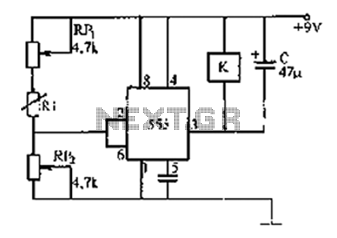
The 555 timer integrates both analog and digital functions within a scaled integrated device. Typically manufactured using a bipolar process, it is designated as the 555 timer, while the CMOS version is referred to as the 7555. In addition...
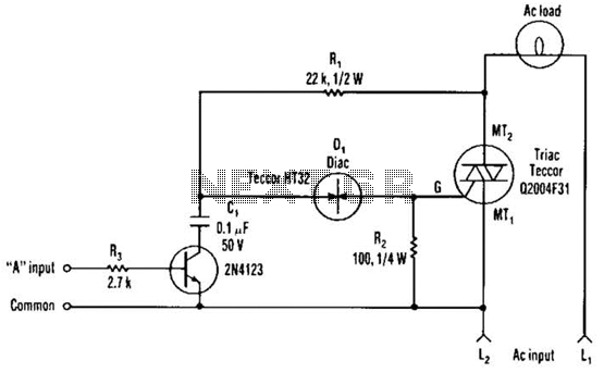
The single transistor connected between the capacitor and the common side of the AC line allows a logic-level signal to control this TRIAC power circuit. Resistor R2 prevents false triggering of the TRIAC by the trickle current through the...
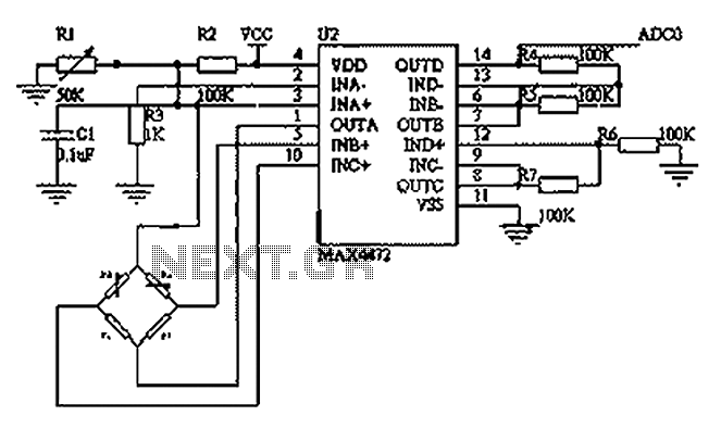
This circuit utilizes a BP01-type pressure sensor and the MAX4472 operational amplifier. The BP01 pressure sensor is specifically designed for blood pressure detection and is primarily used in portable electronic sphygmomanometers. It features a precision thick film ceramic chip...
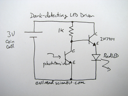
A circuit that uses a phototransistor to create a light-sensitive switch. When there is no light in the room, the LED connected to the phototransistor lights up, and when there is light, the LED turns off. Any schematic or...