
Sensitive rf voltmeter

The RF voltage measurement circuit is designed to operate efficiently in high-frequency applications, specifically in the range beyond 200 MHz. The core component of this circuit is a diode, which is strategically placed in a remote probe. This configuration enhances the accuracy and responsiveness of the circuit, as the diode's proximity to the probe tip allows for minimal signal loss and distortion during measurement.
The circuit is capable of detecting very low voltage levels, with a sensitivity threshold that permits the measurement of RF voltages as low as 1 V peak. This makes it particularly useful in environments where signal strength may be weak, such as in certain RF communication applications or in the testing of RF components.
Calibration of the unit is straightforward, involving the connection of the probe input to a known RF voltage source, typically a calibrated signal generator. This allows for precise adjustments to be made using the calibration control, ensuring that the readings from the circuit are accurate and reliable. Proper calibration is essential for maintaining the integrity of measurements, especially in critical applications where precise voltage levels are necessary for effective performance.
Overall, this circuit design provides a robust solution for measuring high-frequency RF voltages, combining sensitivity, ease of calibration, and effective placement of components to achieve high performance in a variety of electronic testing scenarios.This circuit measures RF voltages beyond 200 MHz and up to about 5 V. The diode should be mounted in a remote probe, close to the probe tip. Sensitivity is excellent and voltages less than 1 V peak can be easily measured The unit can be calibrated by connecting the input to a known level of RF voltage, such as a calibrated signal generator, and setting the calibrate control.
Related Circuits
Voltage measurement is a fundamental aspect of electronic technology today, with increasing demands for accuracy and functionality in instruments. This is particularly critical when measuring signals with significant phase differences, as it is essential to ensure the accuracy of...
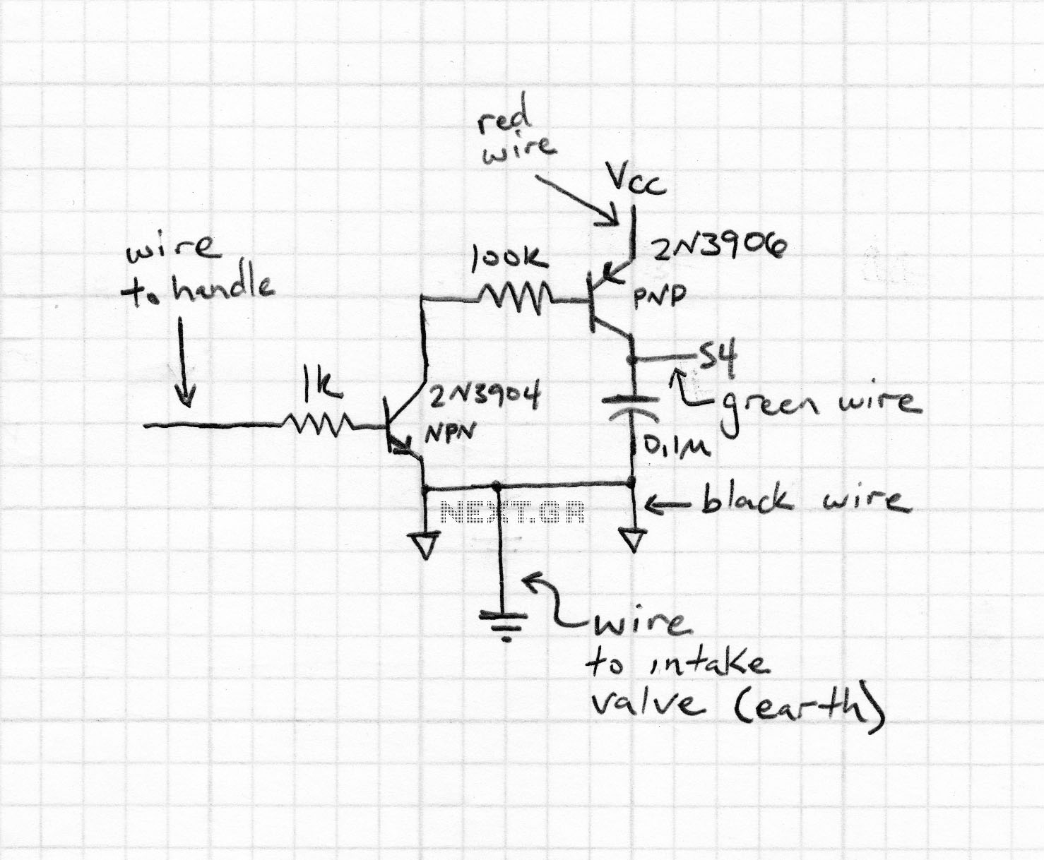
The circuit is a comparator that can measure the voltage of a car battery in steps of 1 Volt. The voltage is determined after comparing the voltage of the battery, which is applied to the inverting inputs of amplifiers,...
This multimeter is designed to measure output voltage and current in a power supply unit (PSU), with the current sense shunt resistor connected in series with the load at the negative voltage rail. It operates using a single supply...
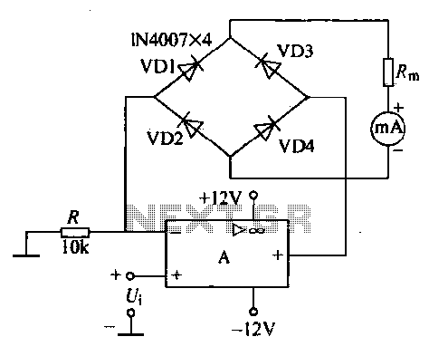
An operational amplifier, a diode bridge rectifier, and DC mA AC voltmeter tables are illustrated in the figure. The operational amplifier used is the LM324. The measured AC voltage is applied to the inverting terminal of the operational amplifier,...
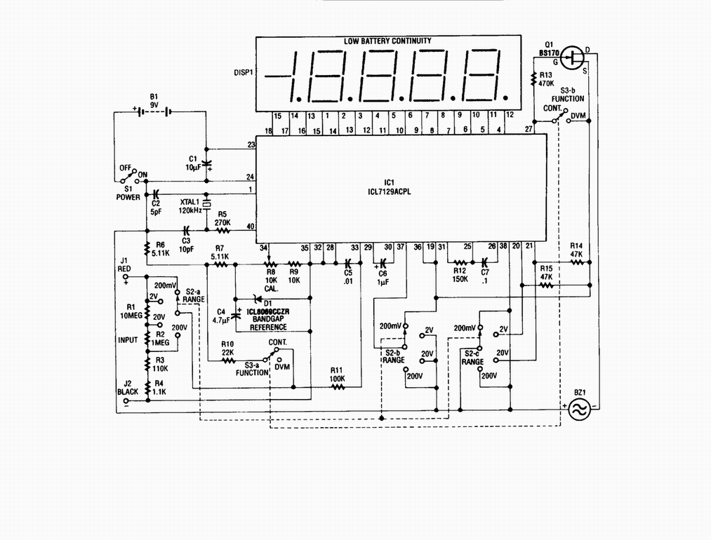
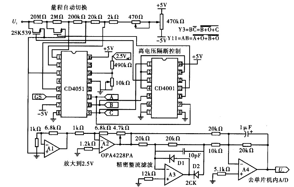
Single-chip digital voltmeter. This 4 1/2-digit DVM circuit is built around a Maxim ICL7129ACPL A/D converter and LCD driver. An ICL8069 CCZR 1.2-V band-gap reference diode is used for accuracy. The described circuit is a single-chip digital voltmeter (DVM) utilizing...
Ensure that connections are verified against the circuit diagram and schematic provided below. This can be utilized while following the tutorial video. The circuit diagram serves as a crucial reference for accurately assembling electronic components in a project. It illustrates...