
The Joule Thief circuit

The circuit design for driving a white LED using a switching power supply involves several key components: an oscillator, a transformer with a ferrite core, a rectifier, and a current-limiting resistor. The oscillator generates a high-frequency square wave signal, which is fed into the primary winding of the transformer. The ferrite core of the transformer enhances the efficiency of energy transfer, allowing for a compact design.
The transformer steps up or steps down the voltage as needed, depending on the specifications of the LED. The output from the transformer is then passed through a rectifier, typically a diode bridge, to convert the AC signal into a DC signal suitable for powering the LED. Following the rectification, a current-limiting resistor is included in series with the LED to ensure that the current flowing through the LED does not exceed its maximum rating, thus preventing damage.
In addition to these components, filtering capacitors may be used at the output to smooth the DC voltage, providing a more stable power supply to the LED. This configuration not only enhances the performance of the LED but also contributes to the overall efficiency of the power supply by reducing losses associated with heat and electromagnetic interference.
The use of a switching power supply for LED applications is advantageous due to its ability to operate efficiently at high frequencies, which allows for a reduction in the size and weight of the overall power supply system. This makes it particularly suitable for portable and compact electronic devices that require effective lighting solutions.In the last post I discussed some of the primary principals of the switching power supply. Essentially an oscillator drives a transformer with a ferrite core at a relatively high frequency, thus minimizing the size, weight, and cost of power supplies. In this project we use the same principals to drive a white LED. 🔗 External reference
Related Circuits
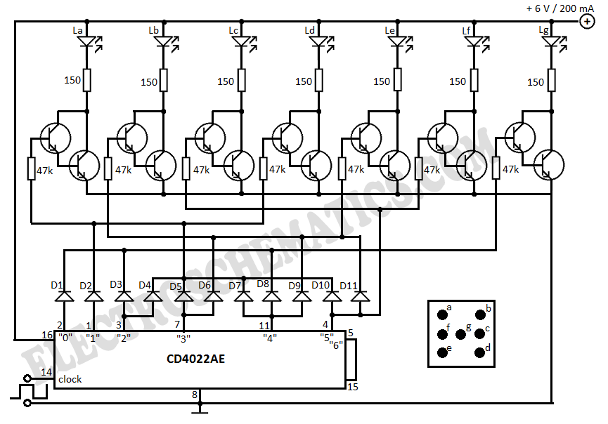
This electronic dice displays results using LEDs arranged to represent each face of a die. The circuit diagram incorporates IC 4022, which functions as a counter. The electronic dice circuit utilizes a combination of integrated circuits and discrete components to...
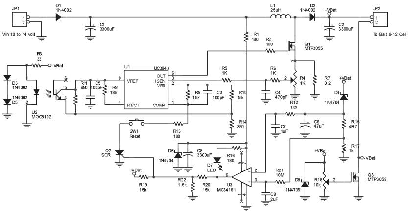
The Ultra Fast Battery Charger for Nickel-Cadmium (NiCad) battery cells is designed to efficiently charge NiCad batteries. This charger, referred to as the Ultra Fast NiCad Battery Charger, is capable of rapidly filling NiCad battery cells. The charger is...
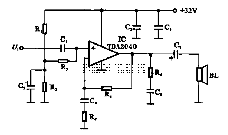
An integrated power amplifier TDA2040 is used in an OTL (Output Transformer-Less) power amplifier circuit, which operates with a +3V single supply as the working voltage. This circuit has a voltage gain of 30 dB (approximately 32 times magnification),...
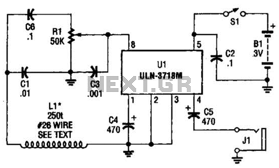
The VLF whistler receiver is designed to detect natural radio noise and signals that occur below 20 kHz. LI is a large loop antenna consisting of 250 to 300 turns of #26 gauge wire wound on a form with...

Power Amplifier Speaker Protection Circuit Schematic. When a power amplifier is switched on, a loud thump sound is often heard due to a sudden heavy discharge. The power amplifier speaker protection circuit is designed to prevent loud thump sounds during...
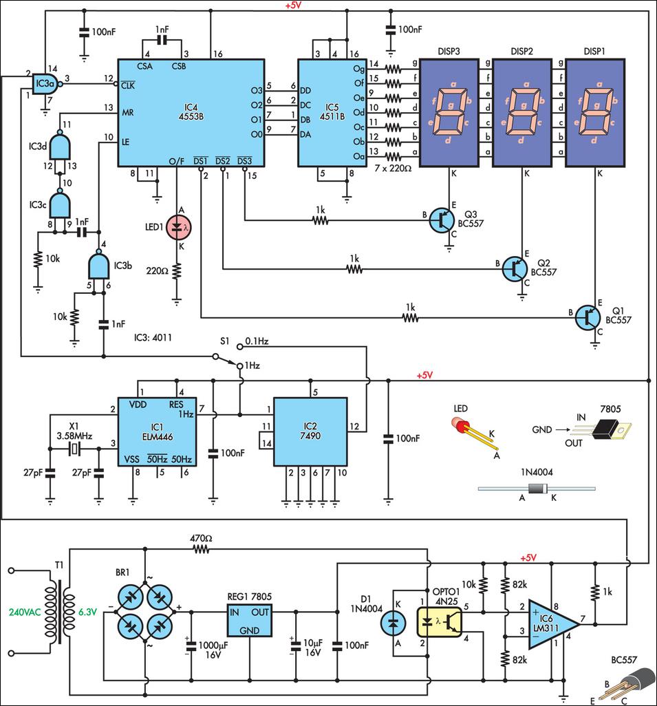
This is a simple frequency counter designed to monitor the 240VAC mains supply. It has a frequency range of 0-999Hz, making it suitable for use with 400Hz equipment as well. Standard TTL/CMOS logic is utilized for the counters and...