
Sequential flasher

This circuit operates as a turn signal flasher system utilizing a combination of transistors and silicon-controlled rectifiers (SCRs) to control the activation of multiple lamps in a sequential manner. The initial activation is initiated by closing the turn signal switch (SI), which causes lamp #1 to illuminate. Concurrently, capacitor C1 begins to charge, and its voltage rise is monitored by transistor Q1. When the voltage across C1 reaches a threshold that exceeds the gate voltage of Q1, Q1 enters a low resistance state, effectively allowing current to flow through the circuit.
Upon activation of Q1, SCR1 is triggered, leading to the illumination of lamp #2 and the commencement of a second timing circuit. This timing circuit may include additional components such as resistors or capacitors that determine the timing characteristics for the sequential operation of the lamps. As Q2 transitions into a low resistance state following the activation of the timing circuit, SCR2 is subsequently triggered, resulting in the illumination of lamp #3.
The thermal flasher component of the circuit plays a crucial role in controlling the overall operation. It periodically interrupts the current flowing to all three lamps, which leads to the commutation of SCR1 and SCR2. This interruption resets the circuit, allowing it to prepare for the next activation cycle. The design ensures that the lamps operate in a coordinated manner, providing a clear visual indication during signaling while also incorporating a timing mechanism that prevents simultaneous activation, thereby enhancing safety and functionality in automotive applications.When the turn signal switch SI is closed, lamp #1 will be activated and capacitor Cl will charge to the triggered voltage of Ql. As soon as the anode voltage on Ql exceeds its gate voltage by 0 V, Ql will switch into the low resistance mode, thereby triggering SCR1 to activate lamp #2 and the second timing circuit.
After Q2 switches into the low resistance state, SCR2 will be triggered to activate lamp #3 When the thermal flasher interrupts the current to all three lamps, SCR1 and SCR2 are commutated and the circuit is ready for another cycle.
Related Circuits

By using three 555 ICs, three sequential pulses can be generated. Output 3 can be connected back to the trigger input to achieve astable operation. The circuit described utilizes three 555 timer integrated circuits (ICs) configured to generate three sequential...
This is a simple 1.5V powered LED flasher circuit diagram. This circuit can flash 1.7V or 2.3V LEDs (depending on the color) using a 1.5V DC input. The LED will turn on when the 100µF capacitor is charged by...
The motor vehicle steering flasher described in the example utilizes high-power transistors as electronic switches, and the circuit is simple and easy to construct. The motor vehicle steering flasher consists of the flash circuit with resistors R1-R3, a capacitor...

This circuit is designed as a warning flasher to alert road users to dangerous situations in low-light conditions. It can also function as a bicycle light, subject to applicable traffic regulations. White LEDs are recommended for use as a...
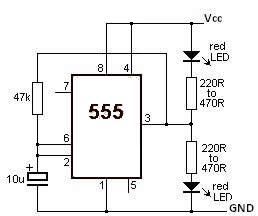
This LED flasher circuit utilizes the 555 timer integrated circuit (IC). The circuit diagram is straightforward and requires only a few external components. When operational, the red LEDs will flash sequentially at a predetermined frequency, similar to the indicators...

The article explains a straightforward method for creating an incremental LED bar graph using the IC 4017, which has specifications that may not fully align with current requirements. It discusses how to modify the IC for these operations. The...