
sequential timer

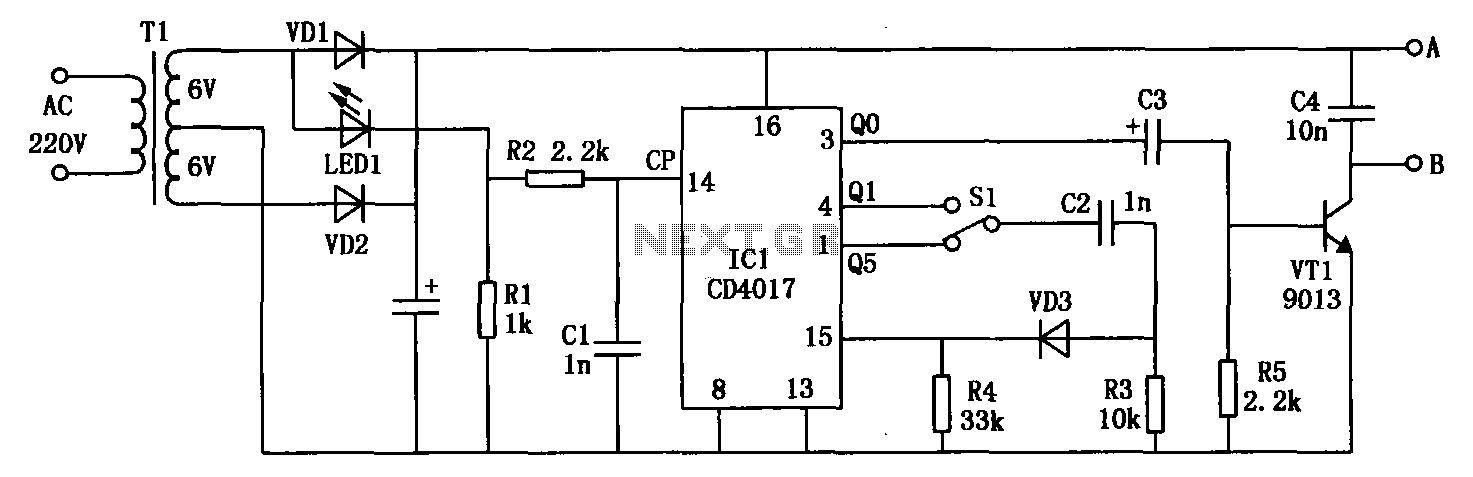
The circuit design incorporates a CMOS 4017 decade counter, which is a versatile device capable of counting pulses and generating multiple output signals. The configuration allows for the selection of different output pins to create a sequence of events. The flexibility in the number of events and their durations is achieved through the use of external resistors and capacitors that define the timing characteristics.
The output pins (3, 2, 4, and 7) are connected to the respective resistors (R1, R2, R3, R4), which limit the current flowing to the next stage, typically a transistor switch. This transistor can control higher power devices, such as relays or buzzers, ensuring that the output from the CMOS counter can interface with various loads.
The timing component of the circuit is critical for determining the duration of each event. Capacitor C5, combined with the resistors R5, R6, R7, and R8, forms an RC timing circuit. The charging and discharging of C5 dictate how long each output remains active. The initial discharge through Q1 introduces a delay before the timing cycle begins, which must be accounted for in the overall timing calculations.
The use of standard values for resistors and capacitors allows for easy replication of the circuit. However, variations in component tolerances can lead to differences in timing. Therefore, empirical testing is recommended to refine the timing values for specific applications. The calculated relationship between resistor and capacitor values provides a guideline for adjusting the timing to meet specific requirements, making this circuit adaptable for various applications requiring timed event sequences.This circuit uses a Cmos 4017 decade counter to create a sequence of four separate events. The number of events in the sequence may be increased to nine or ten. And the length of each event is controlled independently. You`re not limited to a series of - "one after the other" - events. You can produce More Complex Sequences - with overlapping and repeating events. You can also fix the total number of times your sequence will repeat - as well as the point in the sequence where the repetition will stop. The four outputs are taken from pins 3, 2, 4 & 7 - in that order. The current available from each output pin is controlled by R1, R2, R3 & R4. Each resistor will supply more than enough current to operate a transistor switch. And the switch can be used to energize a relay - sound a buzzer etc. The individual output times are controlled by the value of C5 - and the values of R5, R6, R7 & R8 respectively.
At the beginning of each event - Q1 discharges C5. Then the relevant timing resistor takes over - and charges C5 up again. I used a 470uF capacitor in the prototype. And with the resistor values shown in the diagram - the events lasted 38 seconds, 67 seconds, 49 seconds and 9 minutes - respectively. These times each include an initial delay of about 14 seconds - while Q1 discharges C5. Until Q1 switches off - the timing resistors cannot begin to charge C5. Manufacturing tolerances mean that your results are likely to be different from mine. However - because you`re always using the same capacitor to activate the same input pin - the length of each step in your sequence should be fairly predictable.
All you need is one reliable practical observation. Then you can calculate the rest. I got roughly 12 seconds for every 100k/100uF combination. So a 1M resistor and a 100uF capacitor will give about 120 seconds - or two minutes. To this must be added the initial 14 seconds - while Q1 discharges C5. If you want to shorten this discharge time - reduce the value of R11. There`s no theoretical limit on the size of C5. With the 470uF capacitor and the 1M resistor I got just under 9 minutes. So - with a 4700uF capacitor - the 1M resistor should give me just under 90 minutes. And if I increase the resistor to 4M7 - the output should last for around 7 hours. 🔗 External reference
Related Circuits
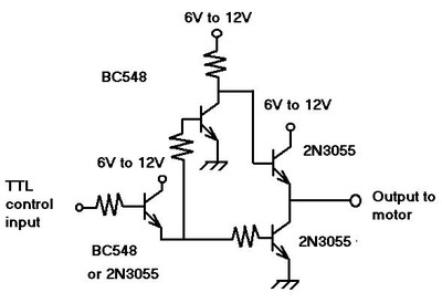
A mechanical engineering student is designing a project that requires a timer to switch off a motor approximately 40-50 seconds after activation. The student references the 555 timer chip, indicating that the chip has a rectangular shape with an...
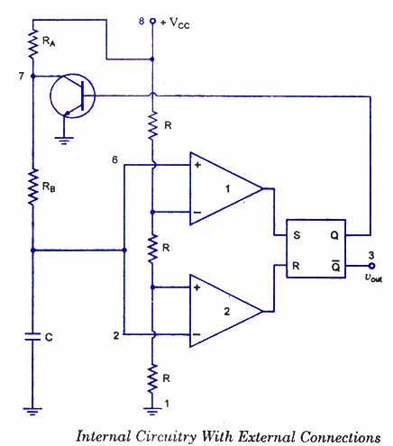
The 555 timer is a highly versatile integrated circuit that can be utilized to construct a wide variety of circuits. It can be effectively used without a detailed understanding of the function of each pin. The 555 timer is commonly...
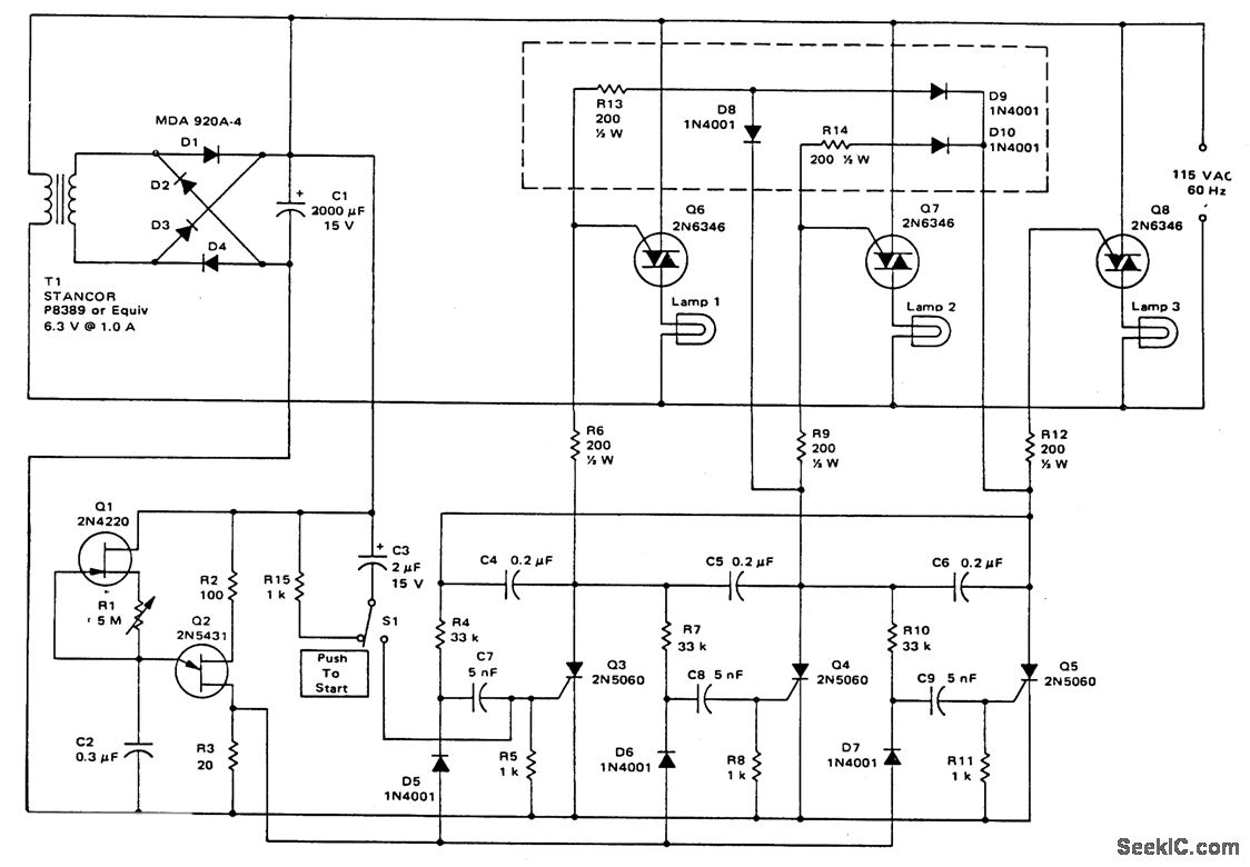
This circuit utilizes a ring counter consisting of Q3, Q4, and Q5. Q2 functions as an oscillator that sequentially triggers the SCRs Q3, Q4, and Q5. When an SCR is activated, a 0.2 F capacitor facilitates commutation, turning off...
This circuit deactivates an amplifier or other devices when a low-level audio signal at its input is absent for at least 15 minutes. By pressing P1, the device is activated, supplying power to any appliance connected to SK1. The...
The electromagnetic RBI timer features a simple structure, is cost-effective, and is commonly utilized in high school physics experiments. However, a significant drawback of the electromagnetic RBI timer is the substantial errors it produces during experiments. This issue arises...
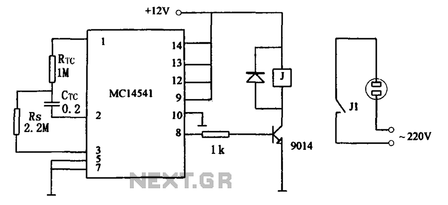
The circuit illustrated in FIG MC14541 is a straightforward timing circuit utilizing the MC14541 integrated circuit (IC). By adjusting the parameter map, the timing can be set for a duration of 3 hours, with options to select various RTC,...