
Serial - parallel conversion circuit
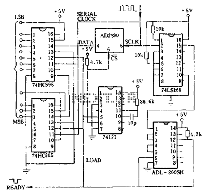
The absolute shaft angle data conversion system outlined involves a serial-to-parallel conversion mechanism for the AD2S90 axis angle data. This conversion is essential in applications where parallel data processing is required for enhanced speed and efficiency. The core of the design consists of two 74HC595 shift registers, which are utilized to store and shift the incoming serial data into parallel format. Each shift register can hold eight bits of data, allowing for efficient handling of the serial input from the AD2S90.
The 74LS169 counter/divider plays a crucial role in managing the timing of the data transfer. This component counts the clock pulses and can be configured to divide the clock frequency, ensuring that the data is synchronized correctly with the output requirements. The use of a 74121 one-shot circuit generates precise timing pulses that are necessary for controlling the data flow. This component is responsible for creating the load pulse, which signals the shift registers to latch the incoming data.
Additionally, a delay circuit is incorporated to ensure that all signals are properly synchronized before data is processed. The selection of the input clock frequency (denoted as SCJ.K) is critical as it determines the rate at which data is sampled and transferred. The generated load pulse (LOAD PULSE) activates the shifting process in the registers, while the chip select pulse (CS) enables the output stage, allowing the parallel data to be accessed by subsequent processing units.
Overall, this circuit design is optimized for high-speed data acquisition and conversion, making it suitable for applications in robotics, automation, and other fields requiring precise angular position measurements. The combination of shift registers, counters, and timing circuits provides a robust solution for converting serial data to a parallel format efficiently.Absolute shaft angle data serial-parallel conversion: the serial AD2S90 axis angle data is converted to parallel data method has many, timed digital pulse signal can be micropr ocessor or a hardware circuit generates. Figure 825 shows an example of using the hardware circuit. Figure 8 26 is a complete circuit diagram. We use two 74HC595 as a shift register, a 74LS169 counter/divider, a 74121 one-shot circuit and a delay when the circuit. Select the correct input clock frequency (SCJ.K), generates a load pulse (J.OAD PULSE), chip select pulse (cs).
Related Circuits
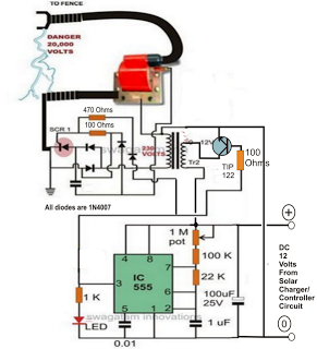
A fence charger or energizer is a device used to electrify a fence or boundary to protect the premises from human or animal intrusions. These boundaries are often located in large fields and parks, typically away from urban areas,...
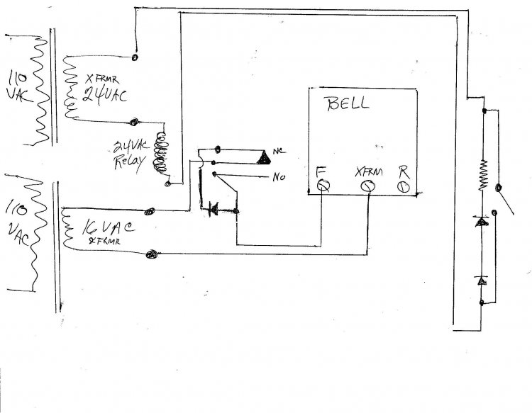
A new wired doorbell has been installed, specifically the Heath/Zenith Model #LE-65-B (Electronic). A new 16 Volt transformer was also added, along with a lighted pushbutton and a diode. Initially, all components functioned correctly, including the lighted pushbutton. However,...

This circuit exhibits an exceptionally fast high-frequency response, as demonstrated by applying a 100 kHz square wave to the input. All graphs were produced using Tina Pro. The circuit's design is optimized for high-frequency applications, showcasing rapid response times that...
The LED flasher circuits operate on a single 1.5-volt battery. The circuit on the upper right utilizes the popular LM3909 LED flasher IC and requires only a timing capacitor and an LED. The LED flasher circuit using the LM3909 integrated...
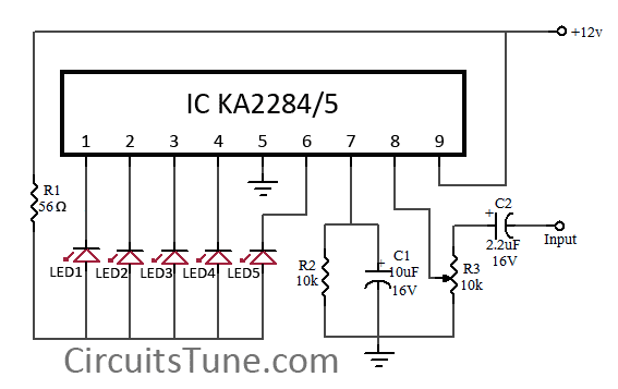
This is a simple circuit diagram of a 5-LED audio VU meter utilizing the ICs KA2284 or KA2285. The KA2284 and KA2285 are monolithic integrated circuits designed as logarithmic display driver ICs. They serve as bar-type display drivers for...
This document details the AT Keyboard Interface and AT Keyboard Protocols. It includes an example of a Keyboard to ASCII decoder utilizing a 68HC705J1A microcontroller. The AT Keyboard Interface is a standard communication protocol used primarily in personal computers to...