
servo motor

To control a standard RC servo motor with a PIC microcontroller, it is essential to generate a pulse-width modulation (PWM) signal that dictates the position of the servo. The PWM signal is characterized by its duty cycle, which determines the angle of the servo arm. Typically, a standard RC servo motor expects a PWM signal with a frequency of approximately 50 Hz, where the pulse width ranges from 1 ms to 2 ms. A 1 ms pulse corresponds to a 0-degree position, while a 2 ms pulse corresponds to a 180-degree position.
The process begins with configuring the PIC microcontroller's timer to generate the PWM signal. For instance, Timer 1 can be set up in the PIC microcontroller to create an interrupt that occurs at a frequency of 50 Hz. The interrupt service routine (ISR) will then toggle a digital output pin connected to the servo control line. The width of the pulse can be adjusted by modifying the timer's compare register, allowing for precise control over the servo's position.
The following steps outline the implementation:
1. **Configuration of Timer**: Set up Timer 1 in the PIC microcontroller to generate interrupts at a frequency of 50 Hz. This involves setting the appropriate prescaler and period values based on the microcontroller's clock frequency.
2. **PWM Signal Generation**: In the ISR, toggle the output pin connected to the servo. The pulse width can be controlled by using a variable that defines the duration of the high state of the output pin. This variable should be set to correspond with the desired angle of the servo.
3. **Mapping Angles to Pulse Widths**: Create a function that maps the desired angle (0 to 180 degrees) to the corresponding pulse width (1 ms to 2 ms). This can be achieved through a linear interpolation based on the angle input.
4. **Output to Servo**: Ensure that the output pin is connected to the control line of the servo motor. The servo will respond to the PWM signal by adjusting its position according to the pulse width received.
5. **Testing and Calibration**: Once the circuit is assembled, it is crucial to test the output signal with an oscilloscope to confirm that the pulse widths are accurate and correspond to the desired angles. Calibration may be necessary to account for any discrepancies between the expected and actual servo positions.
By following these steps and ensuring proper configuration of the PIC microcontroller, a reliable control signal for a standard RC servo motor can be generated, enabling precise movement and positioning in various applications.How to generate the signal for contolling a standard (RC) servo motor using a PIC microcontroller.. 🔗 External reference
Related Circuits
The TBA120U is an intermediate frequency (IF) amplifier that includes a symmetrical frequency modulation (FM) demodulator and an audio frequency (AF) amplifier with adjustable output voltage. The AF amplifier features an output for volume control and an input for...
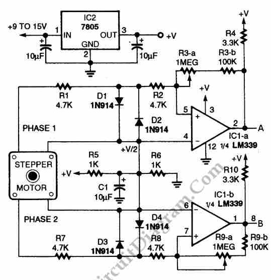
The circuit illustrated in the schematic diagram below allows for the visualization of the direction and shaft rotation of a stepper motor on an LED display. Instead of utilizing a digital rotation encoder as an input, this circuit employs...
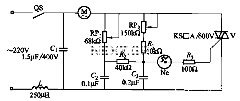
The 3P10 circuit, illustrated in the figure, utilizes a bidirectional thyristor for control. The adjustment potentiometer RPi allows for modification of the minimum motor speed, while the adjustment potentiometer RP2 enables continuous variation of the motor speed, reaching up...

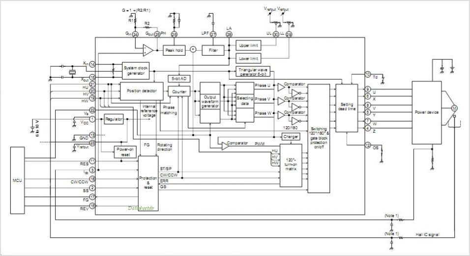
If the control circuit of this motor driver is based on a microcontroller or digital component, it is advisable to implement a buffer for each port that controls the stepper motor driver. This precaution helps prevent overloading the microcontroller...
This add-on circuit enables remote switching on/off of battery-operated toy cars using a TV/video remote control handset operating at 3040 kHz. The described circuit utilizes a remote control system to facilitate the wireless operation of battery-powered toy cars. The primary...
The circuit consists of a 555 motor automatic governor configuration. It includes flip-flops, a 555 timer, and a switching tube. A sampling circuit is formed by connecting R7 and the motor in series. RP1 is used to control the...