
SF04E emission circuit diagram composed SF04B

The SF04E and SF04B remote control transmitter circuits are designed for efficient wireless communication. The SF04E transmitter operates by emitting signals that can be received by the SJ04H matching circuit. This configuration allows for seamless transmission and reception of control signals over a specified range.
In part (A), the SF04E transmitter is detailed, highlighting its key components such as the oscillator circuit, modulator, and the antenna. The oscillator generates a carrier frequency, which is modulated by the input control signal. The modulated signal is then transmitted through the antenna, ensuring effective signal propagation.
Part (B) focuses on the SF04B transmitter circuit, which integrates the SJ04E receiving circuit. This receiving circuit is designed to capture the signals emitted by the SF04E transmitter. Key components of the SJ04E include the demodulator, which processes the incoming modulated signals, and the output stage that translates these signals into actionable commands.
Both circuits are crucial for enabling remote control functionalities in various applications, including consumer electronics and automation systems. The design emphasizes compatibility between the transmitter and receiver, ensuring reliable performance and ease of assembly. The overall schematic illustrates the necessary connections and component placements, providing a clear guide for implementation in practical scenarios. As shown in the circuit diagram SF04E emission and SF04B thereof. (A) shows a remote control transmitter SF04E composition, and it receives the matching circuit can SJ04H assem bly. (B) shows the remote control transmitter circuit consists SF04B composed by SJ04E its composition matching receive circuit.
Related Circuits
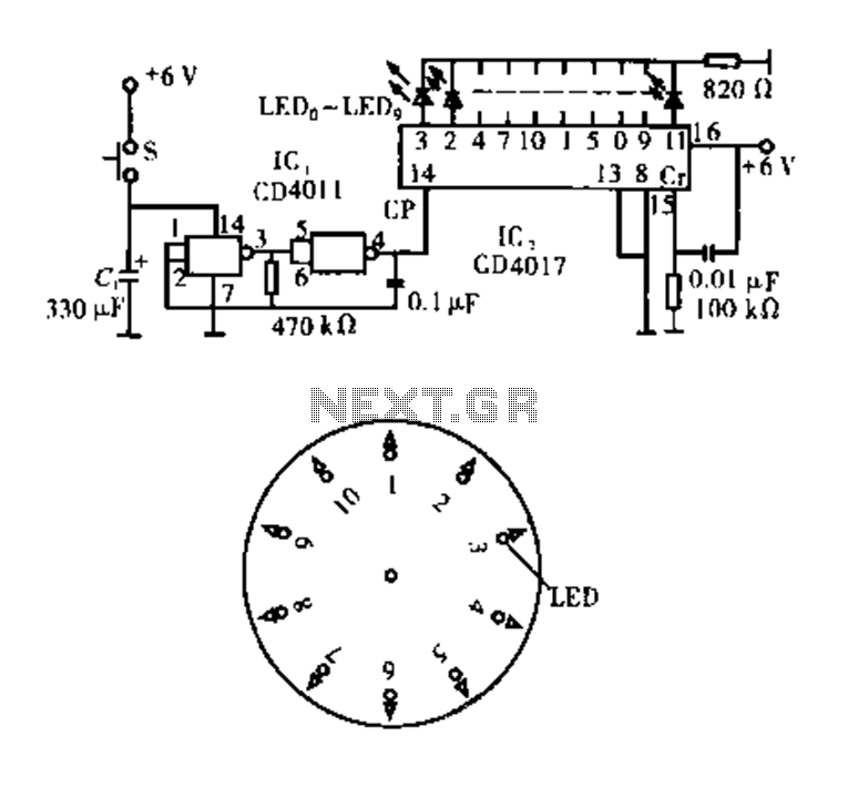
Dot Award. This circuit is tested and functional. The circuit consists of two integrated circuits (ICs). IC1 serves as a pulse source, activated by a momentary button switch (S). When the button is pressed, it charges capacitor C1, which...

The circuit utilizes six 12-volt lead-acid batteries to power the load. Three batteries are connected in series to generate 36 volts, while the other three are connected in parallel to maintain 12 volts. The total discharge current is 30...
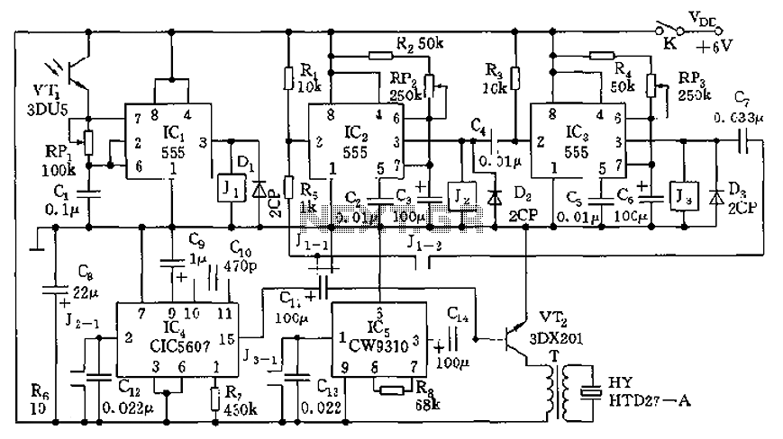
The circuit consists of four light-controlled electronic switches, timing circuits, voice circuits, audio circuits, and other components. It is designed to celebrate birthdays or similar occasions, with features such as birthday candles that can be lit or extinguished. The...
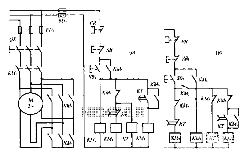
A star-delta switch is utilized for starting circuits, commonly depicted in Figure I-5 (a) of the knife wiring. While this method is effective, it poses security risks. When the motor starts, it can create significant voltage fluctuations that may...
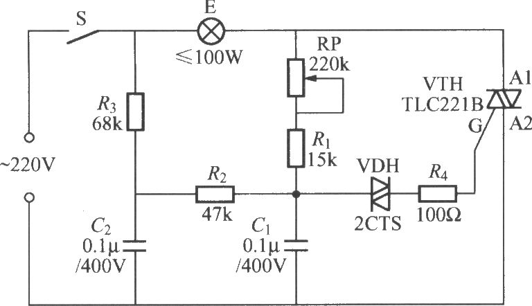
To address the lag and light transition issues, a Triac dimming light circuit featuring a dual time constant can be employed. This circuit enhances the resistor-capacitor network formed by R3 and C2. The reduced charge on capacitor C1 can...
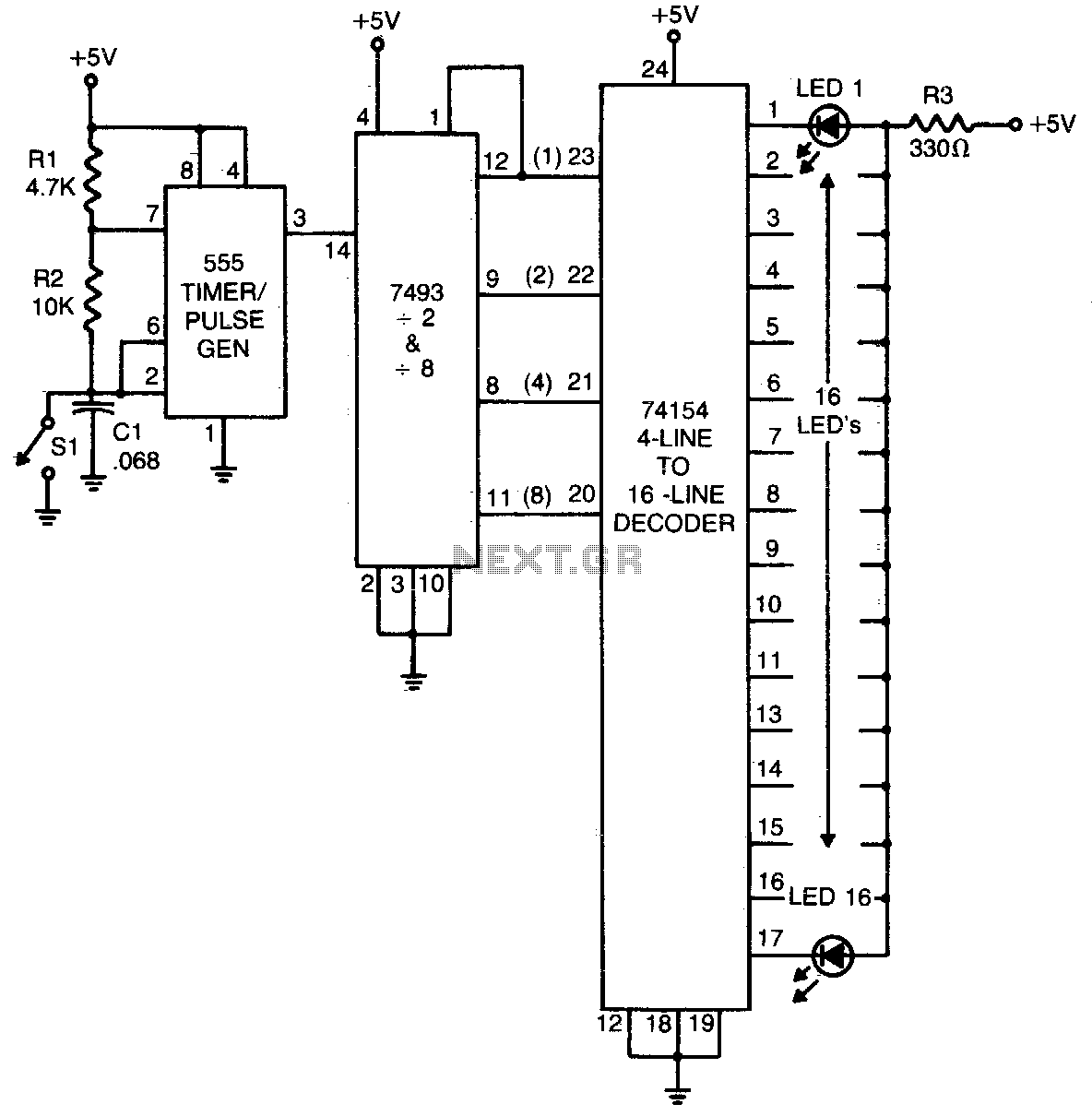
The 555 timer generates a rapid series of pulses when switch SI is in the open position. These pulses are grouped into sets of 16 and converted into binary format by the 7493 counter. The binary output is then...