
To Automate Rolling Shutter Motor

To implement an automated system for a rolling shutter, a time-controlled switch can be utilized to manage the operation of the shutter. The circuit design will involve several key components: a time switch, a relay, and the rolling shutter motor.
The time switch serves as the control unit, allowing the user to set specific times for the shutter to open and close. This device typically features programmable settings, which can be adjusted to meet the user's requirements.
The relay acts as an intermediary between the time switch and the rolling shutter motor. It is essential for handling the higher currents that the motor may draw, ensuring that the time switch, which is rated for lower currents, is not damaged. The relay should be rated appropriately to handle the motor's voltage and current specifications.
Wiring will be necessary to connect these components. The time switch will be connected to the relay's control circuit. The relay's output will then connect to the rolling shutter motor, allowing the relay to control the power supply to the motor based on the time switch's settings.
Additionally, it is advisable to include safety features such as fuses or circuit breakers to protect against overloads. Proper insulation and routing of the wires are also crucial to prevent short circuits and ensure reliable operation.
In summary, the automation of a rolling shutter with a time-controlled switch requires careful consideration of the components, wiring, and safety measures to create an efficient and reliable system.If you would like to automate? the opening and closing a rolling shutter with a time controlled switch, a few additional wires will have to be . 🔗 External reference
Related Circuits
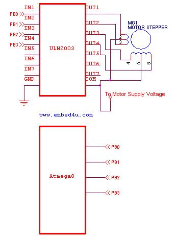
This tutorial utilizes the ATmega8 microcontroller with a 4 MHz crystal oscillator and unipolar stepper motors. The ULN2003, a Darlington pair driver integrated circuit, is employed for motor control. The ATmega8 microcontroller is a versatile 8-bit device from the AVR...
The following circuit illustrates the AC Motor Speed Controller Kit - K2636 Circuit Diagram. Features include standard dimmer functionality, utilizing carbon components. The AC Motor Speed Controller Kit - K2636 is designed to regulate the speed of AC motors, making...
The SM5021 series consists of crystal oscillator module ICs fabricated using NPC's Molybdenum-gate CMOS technology. These ICs integrate high-frequency, low current consumption oscillator and output buffer circuits. They feature highly accurate thin-film feedback resistors and high-frequency capacitors, which eliminate...
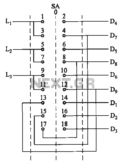
The motor switch control circuit depicted in the figure provides two speed settings for counter-steering, allowing for operation at two speeds in opposite directions. The motor switch control circuit is designed to facilitate the operation of a motor at two...
A nice circuit for using with audio preamplifiers, or any other circuit that use potentiometer and you need to control it from distance. The circuit includes Infrared transmitter and receiver with motor controller chip BA6418N. More: You can use...
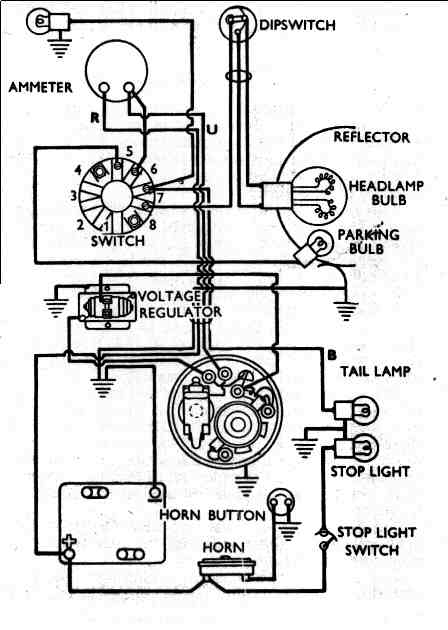
This diagram illustrates a redundant closed-loop ground wiring system designed to minimize reliance on the frame for grounding in the charging circuit. The second diagram depicts the configuration of a bike utilizing a 12-volt Alton generator along with an...