
Shutter tester

The shutter speed tester functions as a precision instrument for measuring the duration of exposure in photographic equipment. It utilizes a crystal oscillator to produce a stable frequency output, which is essential for accurate timing measurements. The frequency counter is employed to tally the pulses generated by the oscillator during the time the shutter is open, providing a direct correlation to the shutter speed.
The photo-transistor-operated gate generator plays a crucial role in this system by detecting the opening of the shutter. When the shutter opens, the photo-transistor is activated, allowing the oscillator's pulses to pass through to the frequency counter. This process ensures that only the pulses corresponding to the open shutter duration are counted, leading to an accurate measurement of the shutter speed.
An important feature of this design is the automatic reset mechanism. As soon as the shutter opens, the system resets itself to prepare for the next measurement cycle. This automation enhances the efficiency of the tester, allowing for quick successive measurements without manual intervention.
In summary, the shutter speed tester is a sophisticated device that combines multiple electronic components to provide precise shutter speed measurements, making it an invaluable tool for photographers and technicians aiming to optimize camera performance.Shutter speed tester combines frequency counter, crystal oscillator, and photo-transistor-operated gate generator. Oscillator pulses are counted as long as the shutter is open Reset is automatic at the instant the shutter opens.
Related Circuits

A simple yet reliable car battery tester circuit diagram. This circuit utilizes the popular and easily accessible LM3914 integrated circuit (IC). The LM3914 is straightforward to operate, does not require external voltage regulators due to its built-in voltage regulator,...
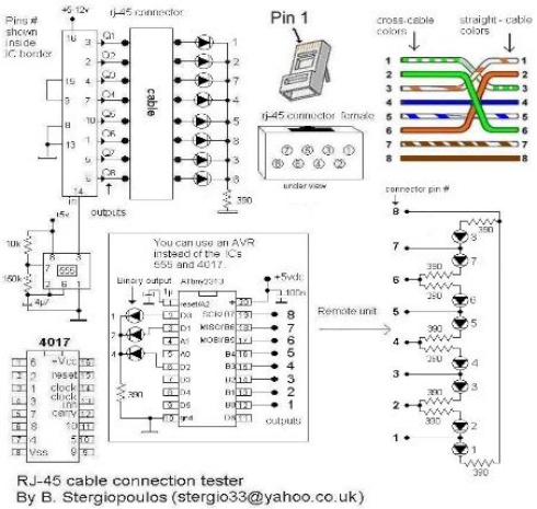
Vasilis Stergiopoulos has developed an RJ45 LAN cable tester. The circuit was initially designed to utilize a 555 timer and a 4017 decade counter IC, but Vasilis has released a schematic and assembly source code for implementing the Attiny2313...
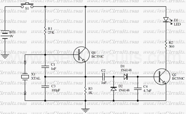
This is a simple XTal tester circuit. T1 and XTal have formed an oscillator. C1 and C2 are voltage divider for oscillator. if the XTal is safe, the oscillator will work well and its output voltage will be rectified...
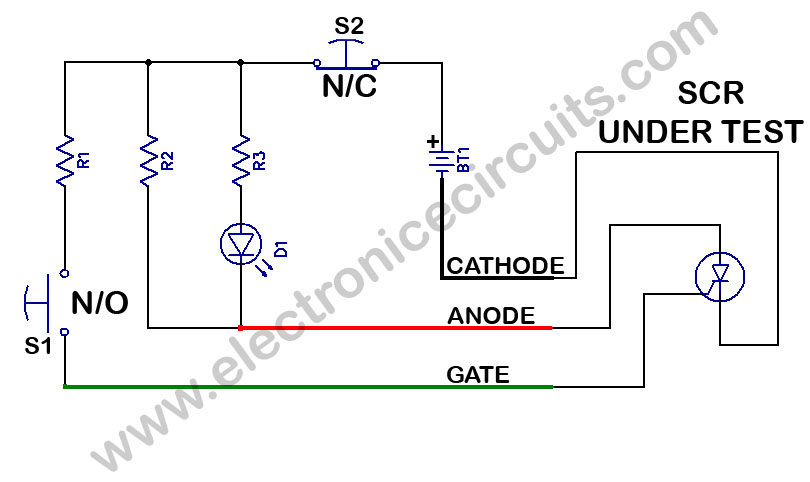
SCR Tester Circuit. The device under test, cathode, anode, and gate are connected to the unit's cathode, anode, and gate terminals. The SCR tester circuit is designed to evaluate the functionality of Silicon Controlled Rectifiers (SCRs) by facilitating connections to...
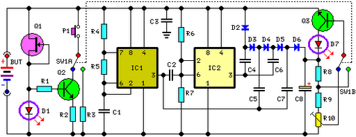
FET Q1 functions as a constant current generator, providing biasing for LED D1 and the base of Q2. This configuration ensures that D1 emits light at a consistent intensity, regardless of the battery voltage, which ranges from 3 to...
Liquid-crystal displays (LCDs) are available in various sizes and configurations, including their pinouts. Many of these displays require the manufacturer's documentation for proper usage, which is often difficult to locate when needed. Consequently, a small tester designed to identify...