
SCR TESTER

The SCR tester circuit is designed to evaluate the functionality of Silicon Controlled Rectifiers (SCRs) by facilitating connections to their cathode, anode, and gate terminals. The circuit typically includes a power supply, a microcontroller or comparator for testing, and visual indicators such as LEDs to signal the SCR's operational status.
To begin the testing process, the SCR's cathode terminal is connected to the designated cathode terminal of the tester, while the anode terminal is linked to the anode terminal of the tester. The gate terminal of the SCR is connected to the gate terminal of the tester.
Upon activation, the tester applies a specific voltage across the anode and cathode to determine if the SCR is in a conductive state. The gate terminal is then energized to trigger the SCR. If the SCR conducts, the circuit will illuminate an LED indicator or display a signal on an LCD screen, confirming that the SCR is functional. Conversely, if the SCR does not conduct when triggered, the tester will indicate a fault.
In addition to basic functionality testing, the circuit may incorporate features for measuring the gate trigger voltage and the holding current, providing further insights into the SCR's performance characteristics. This comprehensive testing capability ensures that the SCRs are reliable for use in various applications, such as in power control and switching circuits.SCR TESTER CIRCUIT The Device under test cathode, anode and gate are connected to the unit`s CATHODE, ANODE and GATE terminals,.. 🔗 External reference
Related Circuits
This circuit allows for the testing of quartz resonators within a frequency range of 32 kHz to 24 MHz. The operational status of the quartz resonator is indicated by a diode signaling an LED and an acoustic signal. The circuit...
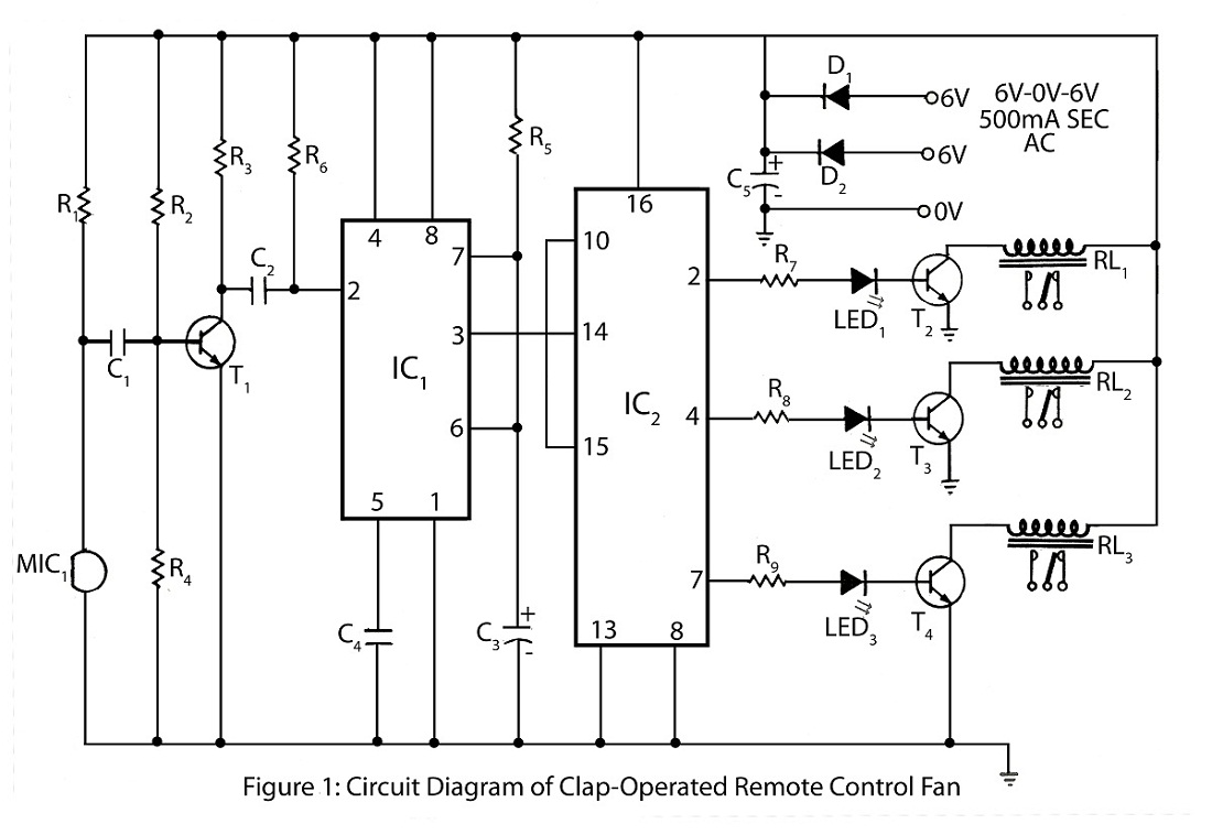
The clap-operated remote control for fans is designed to control a ten-step speed fan circuit. This includes a circuit diagram and a description of the clap-operated remote control system for fans. The clap-operated remote control system utilizes sound recognition to...
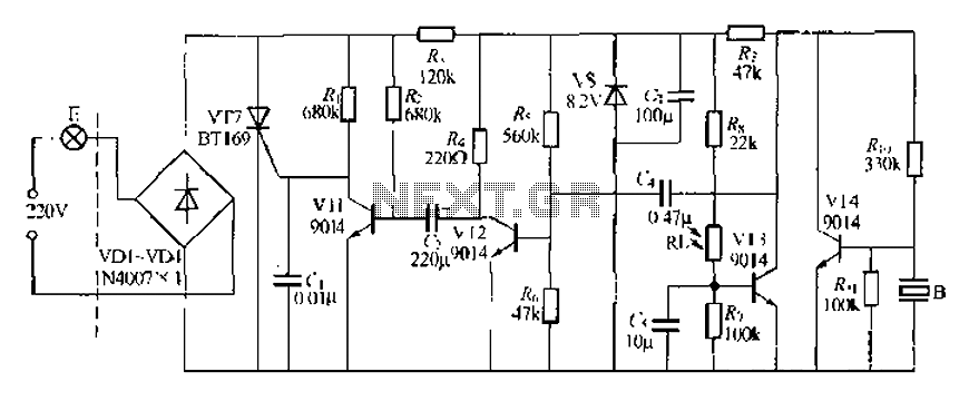
A modified piezoelectric ceramic acoustic-electric transducer is utilized to create a sound and light control system for a stairway walkway with a delay lighting switch. The circuit structure is relatively simple, consisting of diodes VD1 to VD4 and a...
A simple and easy telephone line tester circuit that can be used for testing telephone lines. The telephone line tester circuit is designed to verify the functionality and integrity of telephone lines. It typically comprises a few essential components, including...
This is a simple logic probe circuit. A logic probe is used to determine if a point in a circuit has a high or low state when the circuit is in operation. The logic probe circuit is a fundamental tool...
The heating element is connected in series with two back-to-back 16 amp silicon-controlled rectifiers (SCRs), which are controlled by a small pulse transformer. This pulse transformer features three identical windings: two are dedicated to providing trigger pulses to the...