
Signal Generator Electronic

The signal generator circuit is designed to produce various types of electrical signals, which can be sine, square, or triangular waves, depending on the configuration of the components used. Typically, this circuit includes a function generator IC, such as the 555 timer or a dedicated waveform generator IC, along with passive components like resistors and capacitors that determine the frequency and amplitude of the output signal.
In the case of a 555 timer configured in astable mode, it generates a square wave output. The frequency of the output can be calculated using the formula:
\[ f = \frac{1.44}{(R1 + 2R2)C} \]
where \( R1 \) and \( R2 \) are the resistances connected to the timing capacitor \( C \). The duty cycle, which defines the proportion of time the signal is high versus low, can be adjusted by varying the values of \( R1 \) and \( R2 \).
For sinusoidal output, a more complex arrangement may be needed, often using operational amplifiers to shape the waveform appropriately. The circuit may also include a low-pass filter to smooth out the output signal, ensuring that it closely resembles a sine wave.
The output of the signal generator can be connected to various loads or circuits for testing and experimentation purposes. Proper consideration should be given to the output impedance and the load characteristics to ensure signal integrity. Additionally, power supply requirements should be clearly defined, as they can affect the performance and stability of the generated signals.
Overall, this signal generator circuit is a versatile tool in electronics, suitable for various applications including testing, signal modulation, and waveform analysis.This circuit shows about Signal Generator Electronic Circuit Diagram. Features: UNLESS OTHERWISE SPECIFIED, RESISTANCE VALUES ARE IN OHMS, .. 🔗 External reference
Related Circuits
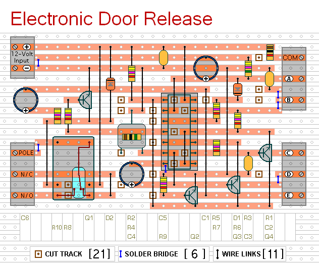
This circuit is designed to operate an electrical door-release mechanism, but it can be adapted for other applications. Upon entering a four-digit code of the user's choice, the relay will energize for a preset duration. The relay contacts can...
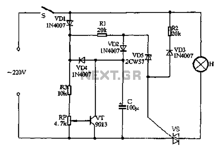
Closing switch S allows the power supply's positive half cycle to flow through VD1, R1, and VD2 to charge capacitor C. The voltage across capacitor C gradually increases but remains significantly lower than the threshold voltage of the zener...
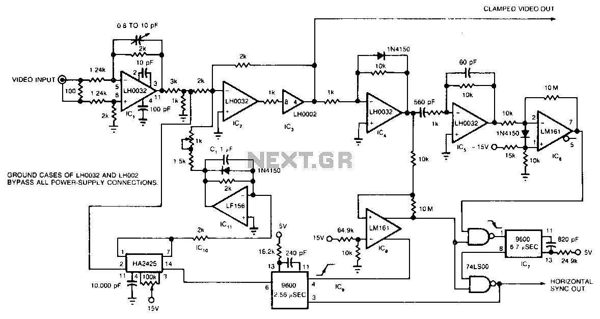
The circuit utilizes a track-and-hold amplifier in a closed-loop configuration to clamp the back-porch voltage of a standard video waveform to 0 V. The outputs of the circuit include a clamped composite video signal and a TTL-level horizontal blanking...
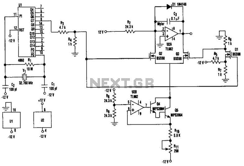
U2-a, U3, and R2 function as an integrator. Q2 and Q3 are alternately switched at 256 cycles. U2-b, Q4, Q5, and R8 through R11 form a constant current generator, with R11 configured to produce a symmetrical triangular waveform. The circuit...
This is an 8-input by 1-output audio/video switch module that can be controlled from a computer, such as through the parallel port. Each audio/video output can be switched to any of the 8 inputs independently. One module drives one...
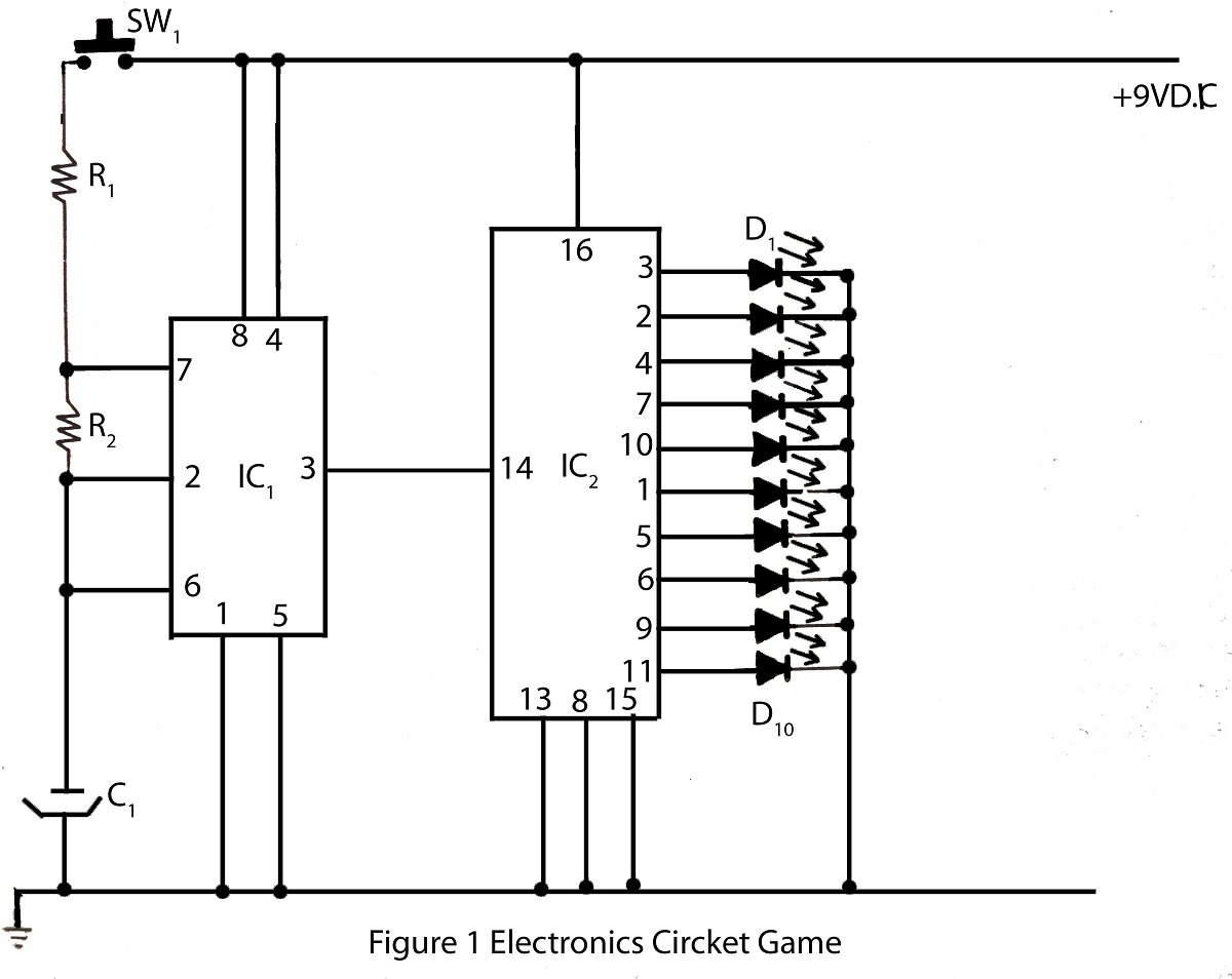
The electronics cricket game circuit presented on this website is a straightforward and easy-to-build circuit diagram for an electronics cricket project, as well as various other game projects. The electronics cricket game circuit typically consists of several key components that...