
Simple 555 Timer Monostable Circuit

The circuit utilizes a 555 timer in monostable mode to control a relay with a momentary normally open (N/O) push button. The design allows for flexible timing based on the capacitor values and resistor configuration. When the push button is pressed, the 0.1 µF capacitor charges, pulling the trigger pin (pin 2) of the 555 timer low. This transition triggers the timer, which causes the output at pin 3 to go high, energizing the relay. The relay remains activated for a duration determined by the RC time constant formed by the 22 µF capacitor and the internal resistor values.
The idle state of the circuit ensures that the relay is deactivated when not in use. The 100K resistor connected to pin 2 maintains a high state until the button is pressed, ensuring reliable triggering. The discharge path for the timing capacitor through the 2K resistor provides controlled discharge, preventing excessive current that could potentially damage the components or create unwanted noise in the circuit.
In applications where longer timing is required, the 555 timer can be configured with larger capacitance values, while for shorter timing, the initial switch closure can be isolated using the 0.1 µF capacitor. This design allows the switch to remain closed without affecting the timing cycle, providing versatility in operation.
The circuit is capable of driving loads up to 200 mA, making it suitable for various applications beyond just relays, including small lamps and doorbells. The diode placed across the 100K resistor serves as a protective measure, ensuring that the voltage at the trigger pin does not exceed the supply voltage during capacitor discharge. This careful consideration of component values and configurations ensures the reliability and functionality of the circuit in practical applications.The two circuits below illustrate using the 555 timer to close a relay for a predetermined amount of time by pressing a momentary N/O push button. The circuit on the left can be used for long time periods where the push button can be pressed and released before the end of the timing period.
For shorter periods, a capacitor can be used to isolate the switch so that only the initial switch closure is seen by the timer input and the switch can remain closed for an unlimited period without effecting the output. In the idle state, the output at pin 3 will be at ground and the relay deactivated. The trigger input (pin 2) is held high by the 100K resistor and both capacitors are discharged. When the button is closed, the 0.1uF cap will charge through the button and the 100K resistor which causes the voltage at pin 2 to move low for a few milliseconds. The falling voltage at pin 2 triggers the 555 and starts the timing cycle. The output at pin 3 immediately moves up to near the supply voltage (about 10.4 volts for a 12 volt supply) and remains at that level until the 22 uF timing capacitor charges to about 2/3 of the supply voltage (about 1 second as shown).
Most 12 volt relays will operate at 10.4 volts, if not, the supply voltage could be raised to 13.5 or so to compensate. The 555 output will supply up to 200mA of current, so the relay could be replaced with a small lamp, doorbell, or other load that requires less than 200mA.
When the button is released, the 0.1uF capacitor discharges through the 100K and 2K resistors. The diode across the 100K resistor prevents the voltage at pin 2 from rising above the supply voltage when the cap discharges. The 2K resistor in series with the 22uF cap limits the discharge current from pin 7 of the timer. This resistor may not be necessary, but it's a good idea to limit current when discharging capacitors across switch contacts or transistors.
🔗 External reference
Related Circuits
The high input impedance, high slew rate, and high voltage characteristics of the CA3140 operational amplifier make it suitable for use in a Wien-bridge sine wave oscillator. The basic circuit configuration for the Wien-bridge sine wave oscillator is depicted...
When a network needs to transfer small blocks of information over long distances, RS-485 is often the preferred interface. Network nodes can include PCs, microcontrollers, or any devices capable of asynchronous serial communications. Compared to Ethernet and other network...
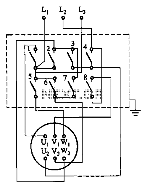
The circuit illustrated in Figure 3-36 includes the starter contact closure detailed in Table 3-1. In the figure, U1, V1, W1, and U2, V2, W2 represent the first three-phase stator windings of the motor terminals. The circuit depicted in Figure...
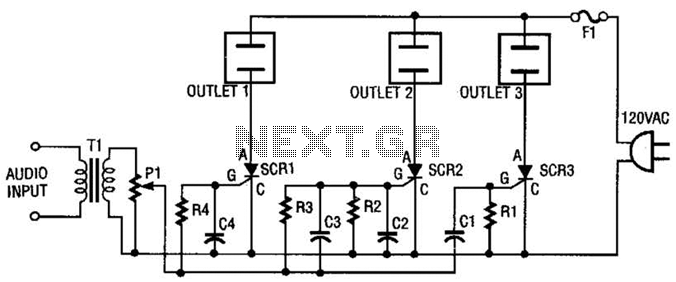
The AC line power is introduced into the circuit through F1, a protective 5-A fuse. One side of the AC line is connected to one side of each AC outlet, while the other side is connected to each silicon-controlled...
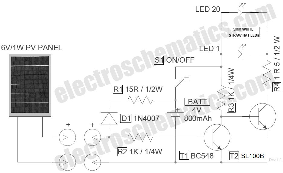
The circuit for the LED solar lantern lights is designed using a 6V/1W solar panel (photovoltaic panel) and a 4V/800mAh lead-acid battery. The schematic for the LED solar lantern circuit incorporates a solar panel that converts sunlight into electrical energy....

To invoke the Spectrum +3 diagnostic routines, first reset the machine while holding the BREAK key down. This will bring up the test card display. Next, hold down the QAZMLP keys for a few seconds until the diagnostic title...