
Simple Am Radio

An AM radio receiver operates by demodulating amplitude-modulated signals to retrieve the audio information transmitted over radio waves. The core components include a diode detector, which rectifies the incoming RF signal, and an audio amplifier, which boosts the audio signal to a level suitable for driving a speaker or headphones.
The antenna, often made from a random length of wire, captures the electromagnetic waves. The effectiveness of the antenna can be enhanced by using an adjustable ferrite loopstick (LI), which is a common element in transistor radios. This loopstick acts as an inductor and is tuned to resonate at the desired frequency, improving the reception of the AM signal.
The diode detector is typically a simple semiconductor diode that allows current to flow in one direction, effectively rectifying the incoming RF signal. After rectification, the audio signal is extracted, which may require additional filtering to remove any remaining RF components. The audio amplifier then takes this signal and amplifies it to a level that can be output through a speaker.
The entire circuit can be powered by a low-voltage power supply, making it suitable for portable applications. Proper grounding and shielding techniques should be employed to minimize interference and enhance overall performance. The design can be further optimized by adjusting the loopstick and antenna length to achieve the best possible reception for various AM broadcast frequencies. An AM radio can be built of a simple diode detector and an audio amplifier. A random length of wire always serves as an ant enna. LI is an adjustable ferrite loopstick of the type used in transistor radios.
Related Circuits
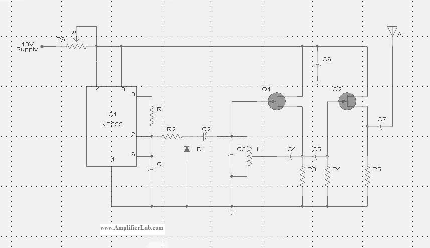
The circuit diagram of the Radio Collar Transmitter is presented here. This circuit is based on the NE555 integrated circuit, which serves as the central component. The Radio Collar Transmitter circuit utilizes the NE555 timer IC to generate a modulated...
This simple tuned radio frequency receiver was designed and constructed in the mid-1990s. The receiver was tested under urban and field conditions, in varying temperatures. This straightforward circuit exhibits high sensitivity, good sound quality, and reliability. A signal received...
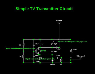
Many individuals inquire about TV transmitters. This document provides a useful circuit diagram that enables signal transmission over distances of 75 to 100 meters. The circuit diagram is not original but was provided by a colleague. Contributions of circuit...
When examining construction notes for building vintage detector-type radios, the specified headphones typically have an impedance of 2 G—2000. In contrast, modern headphones generally have a lower impedance of 2 G—32, which makes them unsuitable for such designs. However,...
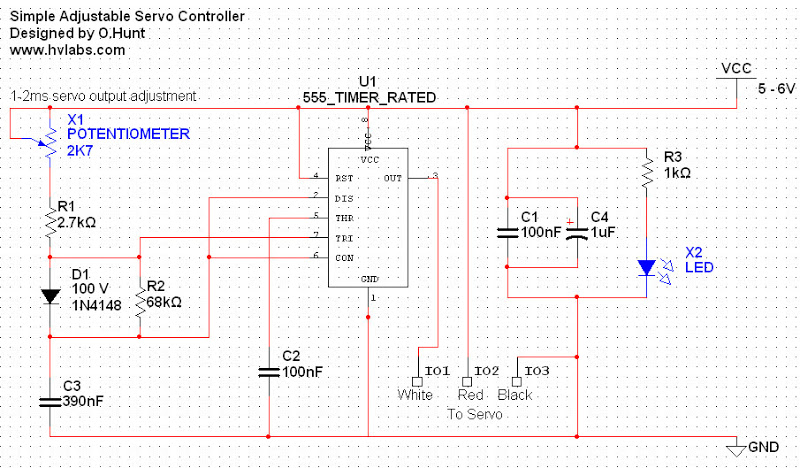
Servos are valuable components for various applications, including robotics, automation, and remote control tasks, such as steering model vehicles. They are relatively inexpensive and readily available; however, controlling them can be somewhat challenging as they require specific timing to...
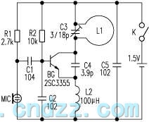
The loop antenna L1 is utilized for emission and also functions as the oscillation coil. The high-frequency current flowing through the antenna is synchronized in resonance with the oscillation frequency, ensuring optimal emission performance. Practical applications indicate that the...