
Simple AM radio

The described AM radio circuit operates on the principle of amplitude modulation, where information is encoded in the amplitude variations of a carrier wave. The tank circuit, composed of the coil L1 and variable capacitor C1, is tuned to the desired radio frequency, allowing the circuit to selectively receive signals. The inductance of L1 and the capacitance of C1 are critical in determining the resonant frequency, which can be adjusted by varying the capacitance.
Transistor Q1 serves as the demodulator, converting the received RF signal into an audio signal. The base of Q1 receives the tank circuit output, where the RF signal is mixed with the local oscillator signal, resulting in the demodulated audio frequency signal. This audio output is weak and requires further amplification to be usable, which is where transistor Q2 comes into play.
Transistor Q2 amplifies the demodulated audio signal from the base of Q1. The amplified signal is then available at the collector of Q2, which can be connected to a speaker or further audio processing circuitry. Proper biasing of both transistors is essential to ensure they operate in the correct regions of their characteristic curves, optimizing performance and preventing distortion.
The circuit's performance is highly dependent on the strength of the incoming radio signal. In environments with strong signals, the circuit will function well, providing clear audio output. However, in areas with weak signals, the circuit may struggle to demodulate the signal effectively, resulting in poor audio quality or complete loss of reception. Therefore, this circuit is best suited for locations with reliable AM broadcast coverage.This is a very simple AM radio circuit using only two transistors. The coil L1 and variable capacitor C1 forms the tank circuit. Transistor Q1 does the job of demodulation. The demodulated signal will be available at the base of Q1. This audio signal is coupled to the base of Q2 for further amplification. The amplified audio signal will be availabl e at the collector of Q2. Please note that, this circuit will work properly only in places with good signal strength. 🔗 External reference
Related Circuits
The frequency range is 100-108 MHz. The circuit is a mono circuit that accepts audio input from either a microphone or another source. The input impedance is 1 MΩ, with an input sensitivity of 5 mV and a maximum...
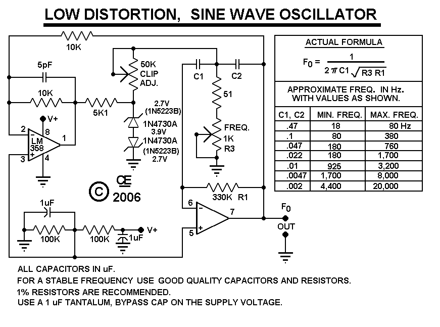
After constructing the device, adjust the frequency to the desired level using the "Frequency Control." Then, utilize an oscilloscope to fine-tune the waveform for optimal performance with the "Clip Control." The sharp rise and fall times of square waves...
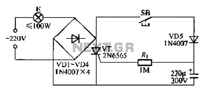
This circuit is a simple connection delay lamp circuit. When the lights are turned on and the switch is pressed, the power supply is activated. The capacitor charges rapidly, causing the thyristor (VT) to open, which in turn lights...
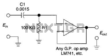
This simple 1 kHz filter utilizes a voltage follower and an RC section as its filtering element. For other frequencies, the -3 dB point is given by the formula 1/(6.28 Rl Cv), and the response decreases at a rate...
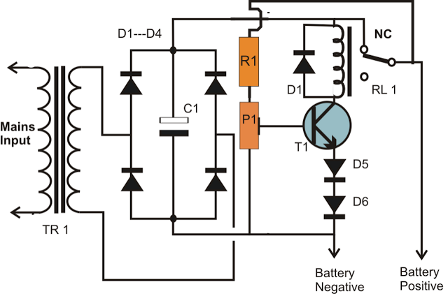
A simple battery charger circuit is described, utilizing a single transistor for voltage detection and automatically disconnecting the battery from the supply when fully charged. The circuit's high voltage trip point is set to switch off the charging voltage...
This circuit is utilized for proximity detection and touch-controlled switching. When a finger approaches the sensor, it generates a capacitance to ground with a value ranging from 30 to 100 pF. Components involved include a resistor, capacitor, diode, and...