
Simple Emergency Lamp

The mini emergency light circuit is designed to operate effectively when integrated with a battery eliminator, ensuring that the voltage supplied is always higher than that of the battery. The use of a power transistor like AD149 for T1 allows the circuit to handle larger loads, making it suitable for applications requiring more intense lighting. The inclusion of a diode serves a critical role in protecting the radio from reverse current during power outages, enhancing the overall reliability of the system.
The LED flasher circuit described is versatile, suitable for various applications, and can be implemented in devices such as stereo amplifiers and decorative toys. The cost-effectiveness of the project, at around Rs 12, makes it accessible for hobbyists and engineers alike. The Schmitt trigger configuration ensures stable switching behavior, while the resistors R1, R3, and R4 allow for customizable timing and brightness settings, accommodating different operational requirements.
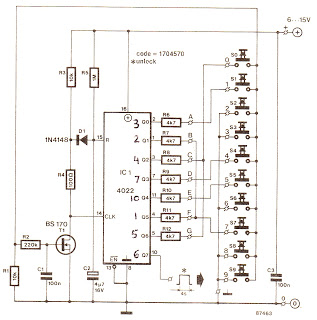
The use of ICs, including the 7490 decade counters and the 7447 BCD to 7-segment decoder, facilitates the counting and display of numerical values in a clear and organized manner. The design emphasizes modularity and simplicity, with local availability of components ensuring ease of assembly. Capacitors C1-C6 play a vital role in maintaining signal integrity by filtering out noise, contributing to the circuit's overall performance.
The power supply section of the circuit, which converts mains voltage to a regulated +5V output, is crucial for the reliable operation of the entire system. The transformer steps down the voltage, while the bridge rectifier and voltage regulator ensure that the output is stable and suitable for powering the digital components of the circuit. The inclusion of current-limiting diodes further enhances the longevity and robustness of the display elements. Overall, this circuit design presents a comprehensive solution for emergency lighting and indication applications.The circuit within the dotted line for a mini emergency light can be incorporated into any battery eliminator, provided the eliminator`s voltage is higher than the battery`s voltage. For greater load (1. e. for more light through a b1gger lamp), Tl should be a power transistor such as ADl49. Diode in the circuit prevents the flow of current from ba ttery in the emergency light to the radio during power failure. It is enough to use the switch in the radio set to tum it off. The following circuit of a simple LED flasher can be used for any indication purpose in stereo amplifiers, tape recorders, fancy dolls etc. All components are locally available and the project would cost about Rs 12 only, apart from power supply.
A Schmitt trigger provides regenerative switching, and Rl gives the necessary charge/ discharge bistable action as Tl is switched on and off. R3 and R4 set the on` and off` times respectively. Brightness of the LED is set by Rl and Vg Depending upon the capacitor, the R-C time constant can be adjusted.
lC3 is similarly fed from IC2. The contents of each decade counter are taken in BCD (binary coded decimal) form, fed through IC 7447 BCD to 7- segment decoder driver and displayed on the corresponding FND 507 LED display. These shaped pulses_are counted by three decade chain counters using three 7490 ICs. Input is given to pin I4 of ICI and output from pin ll of this IC is fed to pin I4 of IC2. Thus the contents of ICI, IC2 and lC3 are displayed one Ll (hundreds), L2 (tens) and L3 (units) I respectively.
Capacitors Cl-C6 are used for noise rejection. A series of three diodes, all lN400l type, have been used for current limiting of the displays and also for maintaining the flow of current in a unidirectional way. Sl resets the counter. Circuit diagram of regulated +5V supply is shown in Fig. 2. Mains voltage is stepped down to 9V AC by transformer xi, rectified by a rectifier bridge comprising four diodes (D4-D7) and regulated to +5V by ICS (7805)
🔗 External reference
Related Circuits

One of the simplest methods of metal detecting is through a beat frequency oscillator. The circuit consists of two balanced oscillators: one provides a reference signal, while the other acts as the detector element. The frequency of the reference...

Fluorescent tubes consume significantly less energy compared to incandescent lamps and have a much longer lifespan. Additional benefits include diffuse, glare-free lighting and reduced heat output. Due to these advantages, fluorescent lighting is commonly preferred in commercial and retail...

Useful for checking diodes, transistors, triacs, SCRs, resistors, and LEDs, this curve tracer should prove beneficial in the experimenter's lab. It displays the volt-ampere characteristic of a two-terminal device on an oscilloscope. This is a simple block diagram of...

A very simple dimmer circuit with only the essentials. In this circuit, the values are given for a BT138 at 220V AC. For 115V AC, experimentation with values may be necessary. R1 can vary from one triac to another;...
The cycle is repeated only when the S7 switch at the Q1 output is pressed within the designated time frame. When all keys are pressed in the correct order and within the specified time, Q7 goes high for approximately...
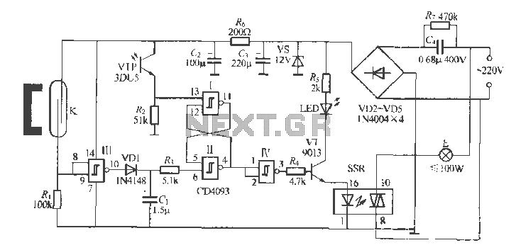
The circuit utilizes multiple integrated circuits to form an automatic lighting device that is activated by door and window sensors. It includes CD4093 digital integrated circuits, a relay, and a power supply circuit. The system typically remains closed when...