
Simple Hybrid Audio Amplifier Circuit

The described amplifier circuit utilizes a BUZ11 MOSFET, which serves as the primary amplification component. This device can be substituted with an IRFZ34N MOSFET, offering similar performance characteristics. The ECC83 vacuum tube, also known as the 12AX7 in the United States, is a dual triode that can replace the ECC88 tube in this configuration.
When using the ECC83, it is critical to adjust the anode voltage to approximately 155 V to ensure optimal performance and prevent damage to the tube. The ECC83 requires a specific operating voltage and current to function effectively, typically drawing around 2 mA per triode section.
In the circuit design, the input stage can be configured to handle low-level audio signals, which are then amplified by the ECC83 before being fed into the MOSFET stage for further amplification. The output stage, driven by the MOSFET, provides the necessary power to drive speakers or other loads, ensuring that the amplifier can deliver the required output without distortion.
Proper biasing of the ECC83 is essential for achieving linear amplification and minimizing distortion. This can be accomplished through a resistor network that sets the appropriate gate voltage for the MOSFET, ensuring that it operates within its linear region. Additionally, coupling capacitors may be employed at the input and output stages to block DC voltage while allowing AC signals to pass through.
Overall, this amplifier circuit design offers flexibility through component substitutions while maintaining performance integrity, making it suitable for various audio amplification applications.Here s an amplifier circuit that based on the BUZ11 can be replaced by an IRFZ34N and an ECC83 can be used instead of the ECC88. In that case the anode voltage should be reduced slightly to 155 V. The ECC83 (or its US equivalent the 12AX7) requires 2 .. 🔗 External reference
Related Circuits
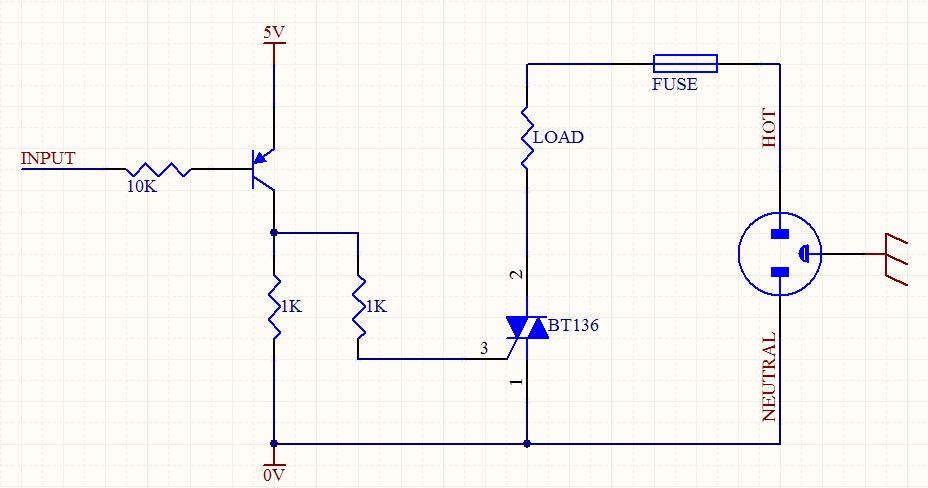
A circuit was designed to function as a light dimmer, utilizing a BT136 SCR and an MOC3022 optocoupler. However, the circuit did not operate as intended. The circuit aims to control the brightness of a light source through phase control...

Building a signal generator is an essential project for any analog DIY enthusiast. While already possessing a bench signal generator, the intention was to create a compact, battery-powered device for quickly testing new effect designs. An enclosure from a...
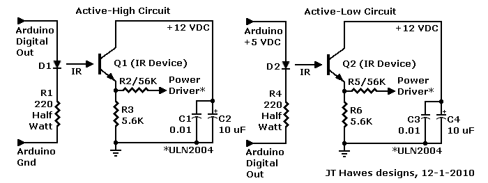
A Darlington transistor can enhance circuit performance, although it introduces slight complexity. The advantage of using a Darlington configuration lies in its capability to achieve low output impedance. The recommended component is the 2N6426 from Mouser, with alternatives such...
This circuit is very basic to build. To open a the lock which is connected to the K1 Load you must press each momentary switch in the correct sequence. The sequence used in this circuit is S1,S2,S3,S4. If any...
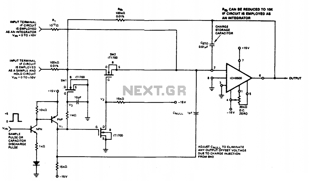
This circuit quickly charges capacitor CST0 to a voltage that matches an input signal. After charging, the input signal is electrically disconnected from the capacitor, allowing the charge to remain on CST0. Since CST0 is part of the negative...
In electronics, filter circuits are primarily used to restrict the passage of certain frequency ranges while allowing other frequency bands to proceed to subsequent stages of the circuit. A high-pass filter circuit permits only frequencies that exceed a specified...