
SPEED CONTROLLER CIRCUIT FOR AC MOTOR

The motor controller circuit is designed to regulate the speed and phase of an AC motor, which is essential for applications requiring precise motor control. The circuit typically includes key components such as capacitors, resistors, and a triac or thyristor for phase control, enabling the adjustment of the motor's speed by altering the voltage and current characteristics.
A common configuration for such a motor controller might include a phase control circuit that utilizes a triac, which allows for the control of the AC waveform delivered to the motor. By adjusting the firing angle of the triac, the effective voltage and current supplied to the motor can be modified, thus controlling the speed. The circuit may also include a microcontroller or a potentiometer for user input, allowing for real-time adjustments to the desired RPM.
Safety features are critical in such designs. A fuse or circuit breaker may be included to protect against overload conditions, while proper heat dissipation measures, such as heat sinks for the triac, ensure reliable operation without overheating. Additionally, snubber circuits may be employed to protect the triac from voltage spikes caused by inductive loads.
The design should also consider the type of AC motor being controlled; for instance, single-phase motors may require different control strategies compared to three-phase motors. Proper filtering and decoupling capacitors can be included to minimize electrical noise and ensure stable operation of the control circuit.
In summary, this motor controller circuit offers a robust solution for varying the RPM and phase control of AC motors, making it suitable for a wide range of industrial and consumer applications.this circuit serves as a motor controller circuit to easily controlling or varying the RPM & Phase control of a AC motor. source: directly 220VAC Load: approx. 1hp AC motor (600w-1kw) CIRCUIT DIAGRAM: COMPONENT PARTLIST: C1 = 2G .. 🔗 External reference
Related Circuits
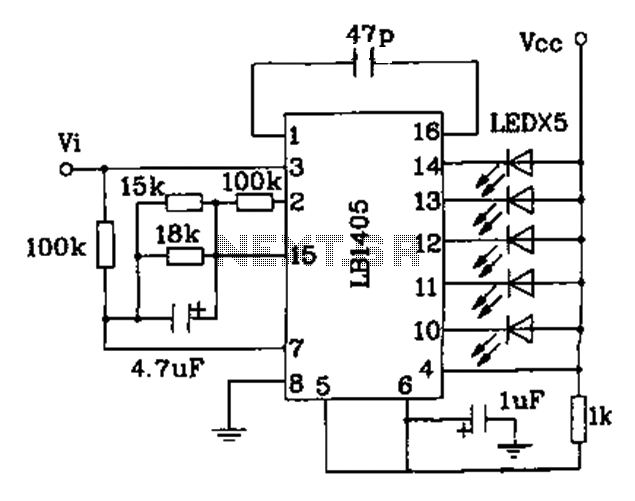
The LB140 is depicted in Figure as a typical driver IC circuit for a five-digit LED level indicator. The BL1405 is commonly utilized in tape recorders for level indication. The LB140 integrated circuit serves as a driver for five-digit LED...
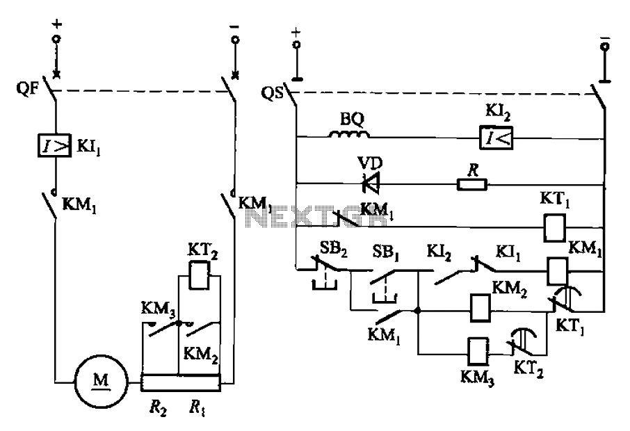
The circuit illustrated in Figure 3-191 features a DC motor armature circuit that includes two series startup resistors, Ri and Rz. The operation of the motor is controlled using buttons for starting and stopping. During the startup phase, two...
The circuit diagram presented is for an IC controlled emergency light with a charger, functioning as a 12V to 220V AC inverter circuit. Key features include automatic activation of the light during a mains failure and a battery charger...
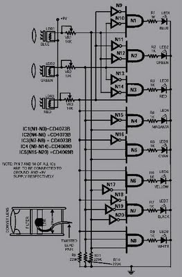
This circuit is capable of sensing eight colors: blue, green, and red (primary colors); magenta, yellow, and cyan (secondary colors); along with black and white. It is designed based on the principles of optics and digital electronics. The object...
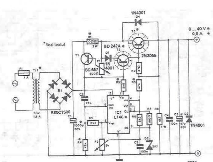
An adjustable laboratory power supply capable of providing an output voltage range from 0 to 60 volts can be constructed using the provided circuit diagram. This power supply can utilize the LM723 chip for lower voltage applications or, for...
This article presents a high reliability 1200V High Voltage Integrated Circuit (1200V HVIC) for half bridge driver applications, aimed at reducing the IC's supply current by approximately 50%. The 1200V High Voltage Integrated Circuit (HVIC) is designed specifically for half-bridge...