
Simple Car theft alarm system circuit using NE555

The utility vehicle anti-theft alarm circuit is designed to enhance the security of vehicles by deterring theft through an audible alarm system. The circuit is fundamentally divided into two key sections: the detection mechanism and the alarm activation system.
The detection mechanism is initiated when the vehicle owner exits the vehicle and activates the anti-theft switch (S B). This switch is typically a normally open contact that closes when engaged, signaling the system to monitor for unauthorized access. If an intrusion is detected, the system triggers the alarm.
The alarm activation system is responsible for generating a loud sound to alert nearby individuals of the potential theft. This may include a piezoelectric buzzer or horn, which is powered by the vehicle's battery. The alarm circuit can be designed to include additional features such as a time delay to prevent false alarms caused by environmental factors, or a flashing LED indicator that visually signals the alarm status.
To ensure reliability, the circuit may also incorporate a backup power source, such as a capacitor or a small battery, which allows the alarm to function even if the vehicle's main battery is disconnected or depleted. Furthermore, the design can include additional sensors, such as door switches or motion detectors, to enhance the security coverage of the vehicle.
Overall, the utility vehicle anti-theft alarm circuit is a crucial component in vehicle security systems, providing peace of mind to vehicle owners through its effective monitoring and alerting capabilities.Utility vehicle anti-theft alarm circuit as shown. It is mainly composed of two major anti-theft alarm circuit parts and components. Security circuit: When the car owner left the car, it will be placed on anti-theft switch S B, and make the.. 🔗 External reference
Related Circuits
This is the basic interface I used as part of my Computerized Room project. This is the parallel interface only. The 8 bit input card can be found, along with the rest of the project, at Computerize Your Room/House....
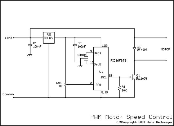
If EAGLE is not available, a full working version can be downloaded from CadSoftUSA. A zip file containing the EAGLE schematics is provided. The EAGLE software is a widely used electronic design automation (EDA) tool that facilitates the creation of...
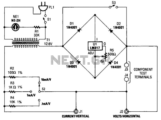
Useful for checking diodes, transistors, triacs, SCRs, resistors, and LEDs, this curve tracer should prove beneficial in the experimenter's lab. It displays the volt-ampere characteristic of a two-terminal device on an oscilloscope. This is a simple block diagram of...
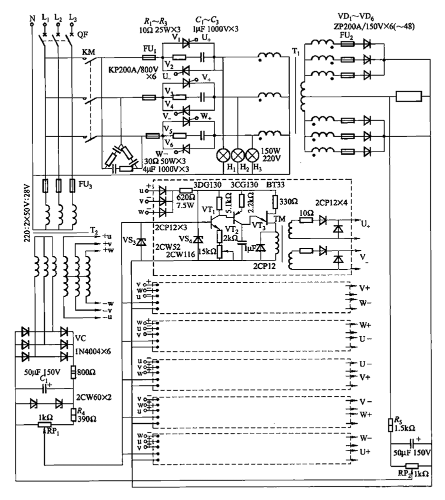
A three-phase thyristor power regulator circuit designed for plating applications, capable of handling currents from 1200A to 6000A at a voltage of 10V. The circuit comprises a main circuit, a trigger circuit, synchronous power components, and a voltage negative...
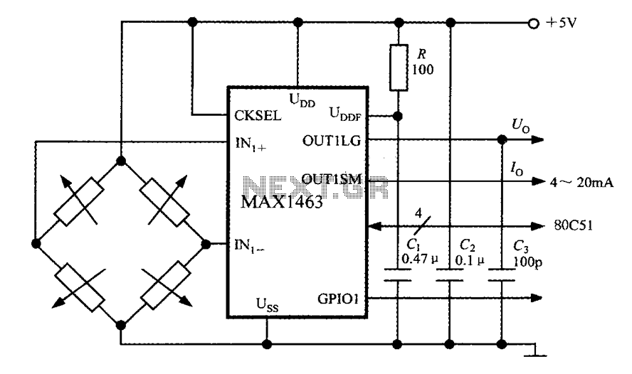
The system consists of a MAX1463 precision pressure detection circuit block diagram. The output voltage from the bridge pressure sensor is connected to the MAX1463 inputs IN1+ and IN1-. Controlled by a CPU, the pressure signal undergoes nonlinear calibration...
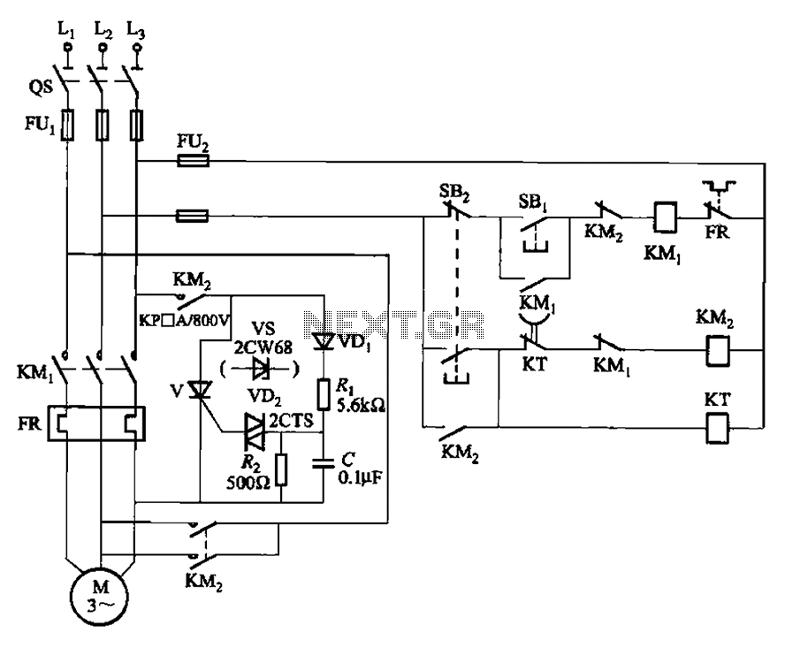
The circuit illustrated in Figure 3-148 eliminates the requirement for a step-down transformer by utilizing a thyristor for brake control in small capacity asynchronous motor braking applications. Upon shutdown, the contactor KM1 releases, while contactor KM2 engages the brake...