
Simple FM Radio with improved audio gain

To create an inductor using solid wire, begin by winding six turns of the wire around a cylindrical object, such as a pen or pencil, which should have a diameter of approximately 0.5 inches. After completing the winding process, carefully remove the coil from the cylindrical form. The next step involves gently spreading the coils apart to achieve a total length of approximately 0.75 inches.
Once the coil is properly shaped, the component labeled C2 should be soldered to the coil. The placement of C2 is critical; it should be positioned near the center of the coil to ensure optimal electrical performance. This configuration allows for effective inductance, which can be utilized in various electronic applications, such as filters, oscillators, or power supply circuits.
The solid wire used for winding should be of an appropriate gauge to handle the current requirements of the circuit while minimizing resistive losses. Additionally, the number of turns and the spacing between them can influence the inductance value, which can be calculated using the formula for inductance based on the coil's physical dimensions and the properties of the wire material. Proper insulation should be considered to prevent short circuits, especially if the coil is to be placed in a compact enclosure with other components.Wind 6 turns of solid wire on a pen or pencil that is just under 1/2 inch in diameter. Remove the wire from the pencil and spread the winding to make a length of 3/4 inch. Solder C2 somewhere near the middle of the coil. 🔗 External reference
Related Circuits
This circuit was designed as a small portable DJ mixer for a friend. It is a simple audio mixer circuit featuring two dual logarithmic potentiometers to adjust input signal levels, along with several resistors for mixing. The circuit operates...
This circuit is a simple analog multiplier. The operation of the circuit can be understood by considering A2 as a controlled gain amplifier. It involves components such as an analog multiplier, a log-antilog circuit, and a summing junction, along...
This simple circuit is designed to detect RF radiation leakage from transmitters, faulty connections, broken cables, or equipment with inadequate RF shielding. It is specifically tailored for the 2-meter amateur radio band (144-146 MHz in Europe). The device features...
Gain adjustment can be made more flexible when controlled by a voltage signal, as this allows for various methods to provide a user interface. The concept of voltage-controlled gain adjustment is integral to many electronic circuits, particularly in audio processing...
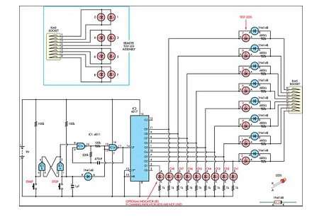
This circuit originated from the necessity for a simple and efficient network tester that could be operated by a single individual. All the commercial units tested required a personal... This network tester circuit is designed to provide a straightforward solution...
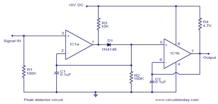
LM339-based peak detector circuit. Simple and easy to construct. Operates from a 5V DC single supply. LM339 is a dual comparator. The LM339-based peak detector circuit is designed to capture and hold the peak value of an input signal. This...