
Combustible Gas Detector Circuit

The gas sensor operates on the principle that the resistance of tin dioxide varies with the concentration of reducing gases, such as methane or propane. As the concentration of these gases increases, the sensor's resistance decreases, leading to a change in voltage across the voltage divider formed by the sensor and R1. This change in voltage is monitored by the comparator circuit.
The comparator circuit typically consists of an operational amplifier (op-amp) configured to compare the voltage from the voltage divider against a reference voltage. When the voltage from the sensor falls below the reference level, indicating a dangerous concentration of gas, the output of the op-amp switches states, triggering the alarm buzzer. This alert system is crucial for ensuring safety in environments where combustible gases may be present.
The choice of R1 is critical, as it must be specifically matched to the characteristics of the gas sensor to ensure accurate detection and response. The manufacturer provides this resistor value to optimize the performance of the sensor in its intended application. In addition to the basic components, the circuit may also include additional features such as LED indicators to visually signal the status of the sensor and alarm system, as well as potential filtering capacitors to stabilize the voltage readings and reduce noise.
Overall, the gas sensor circuit is a vital tool for monitoring air quality and ensuring safety in various applications, including residential, industrial, and commercial environments. The combination of the tin dioxide sensor, voltage divider, and comparator circuit provides a reliable method for detecting hazardous gas levels and activating alarms to alert users of potential dangers. THE GAS SENSOR is mainly composed of tin dioxide on a ceramic base; the resistance of the sensor varies depending on the concentration of reducing gases in the air. The circuit shown is useful for the detection of dangerous levels of combustible fumes or gases. It uses a comparator circuit to trigger an alarm buzzer. The sensor`s resistant element is connected in series with resistor R1 to form a voltage- divider circuit;
R1 is specifically matched to each gas sensor by the manufacturer.
Related Circuits
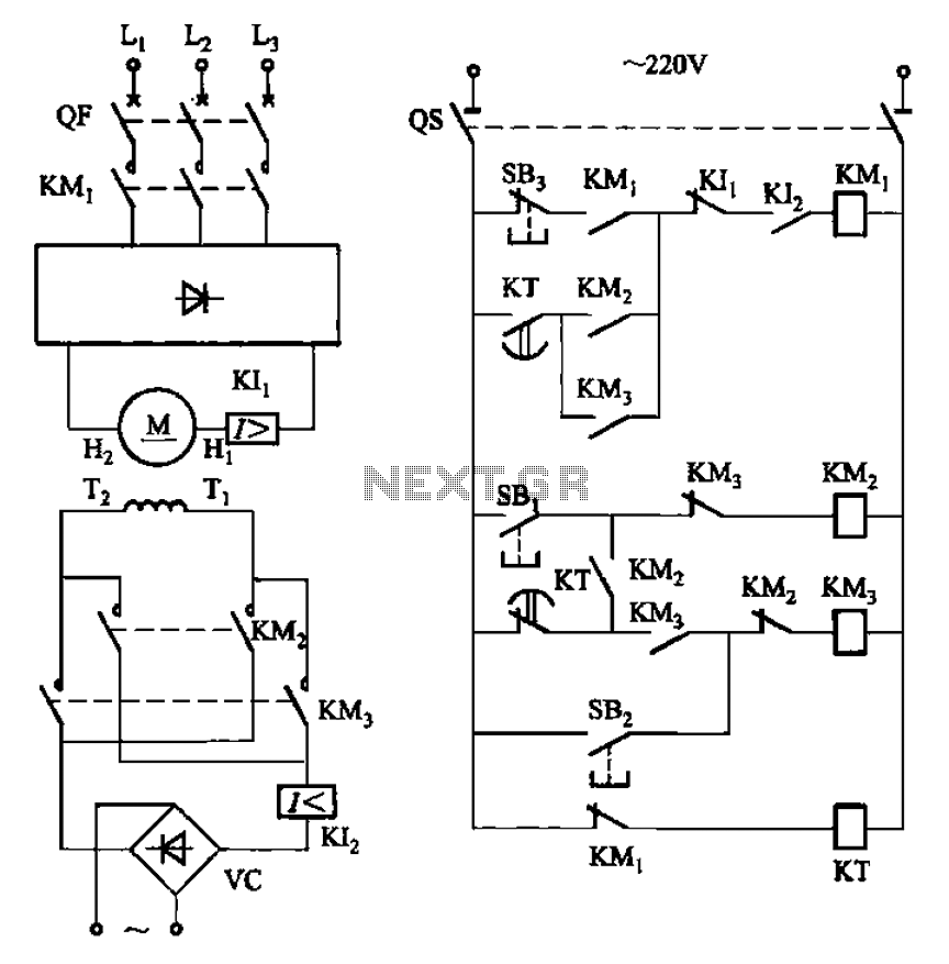
The circuit depicted in Figure 3-193 illustrates a separately excited DC motor. The brake circuit is not activated; therefore, positive reversals occur alternately using a delay action relay, ensuring that the motor reverses direction after coming to a stop. The...

A simple PWM lamp dimmer using the NE555 timer IC. The 555 timer IC is configured as a variable duty cycle astable multivibrator to control the brightness of the lamp. The described circuit utilizes the NE555 timer IC, a versatile...

The circuit illustrated in the schematic diagram below allows for the visualization of the direction and shaft rotation of a stepper motor on an LED display. Instead of utilizing a digital rotation encoder as an input, this circuit employs...
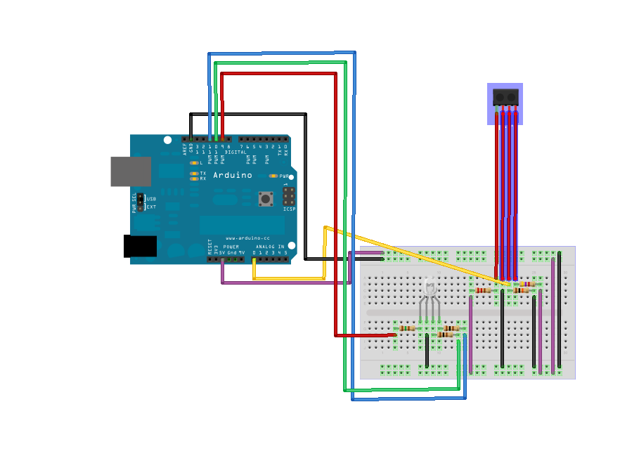
TCRT1000 - Reflective Optical Sensor manufactured by Vishay Semiconductors. This component was ordered from Mouser. For more information, refer to the Sensor Report on the Reflective Optical Sensor TCRT1000. While there are concerns regarding the code and schematic used,...

This circuit generates an output frequency that is linearly proportional to the ratio of two input frequencies. Each pulse of the bias frequency will open a switch for a period equal to half of the second input frequency, allowing...
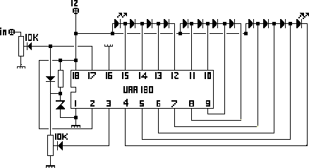
The NL3ASD schematic pages provide the schematics for a LED VU meter utilizing the UAA180 integrated circuit. The NL3ASD schematic pages feature a comprehensive design for a LED VU meter that employs the UAA180 IC, known for its audio signal...