
Simple Code Lock

The described electronic circuit utilizes a Type 4022 octal counter, which is pivotal in the operation of a secure locking mechanism. The circuit is designed to ensure that a specific sequence of key presses must be adhered to for the unlocking process to occur. The S7 switch acts as a trigger that initiates the unlocking sequence only when pressed at the correct time. The output Q7, when activated, provides a signal that can drive an external relay, which in turn can operate an automatic door opener.
In its idle state, the circuit maintains the reset input of the octal counter in a high state through the charging of capacitor C2 via resistor R5. This configuration ensures that only output Qc is active while all other outputs remain low, establishing a stable starting condition for the counter. The pressing of switch S1 introduces a clock pulse to the counter by activating transistor T1 through a debouncing network, which is crucial for preventing false triggering due to switch bounce. The discharge of capacitor C2 through resistor R4 and diode D1 effectively resets the counter, allowing it to count up in response to subsequent key presses.
The locking mechanism's security is enhanced by the flexibility of the combination code, which can be changed by simply altering the connections between the counter outputs and the corresponding switches. This adaptability increases the number of possible combinations, thereby improving security. The circuit's low power consumption of 0.5 µA allows it to be powered by a wide range of supply voltages, making it suitable for various applications where battery life is a concern. The entire design reflects a balance of functionality, security, and efficiency, making it an effective solution for automatic locking systems.The above cycle is therefore repeated only when S7 at the Q1 output is pressed in time. When all keys have been pressed in time and in the correct order, Q7 goes 5 high for about 4 seconds to enable driving the unlock circuitry, e. g. a relay driver for an j automatic door opener. At the i heart of the circuit is the `Type 4022 octal counter. In th e non- active state, Cz is charged via R5, so that the reset (R) input of the counter is kept logic high. This causes output Qc to be actuated, while all other outputs are logic low. When S1 is pressed, T1 is switched on via debouncing network Rz ”C1, and IC1 receives a clock pulse. Also, Cz is discharged via R4-D1, ending the reset state of the counter and enabling it to I advance.
The 5 code for the lock shown in the T circuit diagram is 1704570: this is but an example, however, and i the combination code is readily Y altered by swapping connections between the counter out- puts and the switches. This means that the number of combinations is 109 instead of 107. The quiescent current consumption of the code lock ` negligible at 0. 5 JA, so that the operation is feasible. The circuit works well from any supply between 6 and 15V 🔗 External reference
Related Circuits
To implement a modification that enables automated locking of the Scorpio's central locking system once a preset speed threshold is reached. This enhancement increases security and safety. Various methods exist for calculating the velocity of an object; in this...
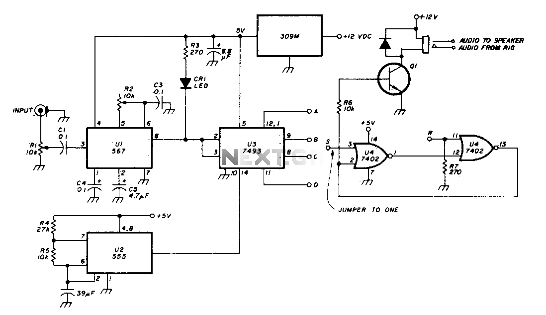
The Phase-Locked Loop (PLL) integrated circuit (U1) is configured with resistor R2 to achieve the desired tone frequency. An LED indicator is used to show when the PLL has locked onto the signal. To ensure proper lock-up, the signal...
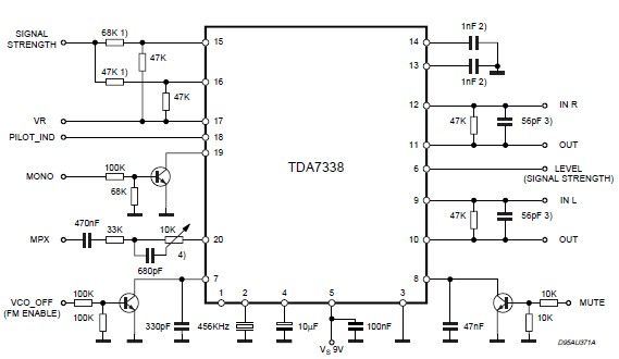
The pilot detector output is configured as an open collector output, requiring an external pull-up resistor. To set the decoder to "MONO," Pin 19 must be clamped to a voltage below 0.8V. The open collector output configuration allows for multiple...
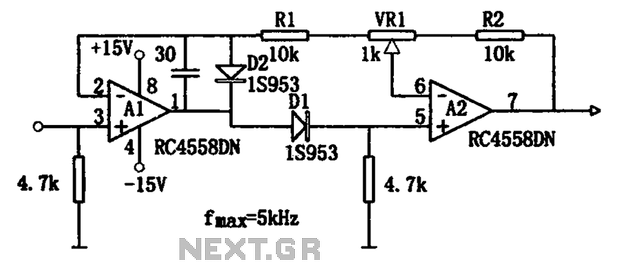
The circuit illustrates a simple method for adjusting the high input impedance of a double wave linear detector. It employs an operational amplifier configured with a negative feedback loop to compensate for the non-linear behavior of the diode used...
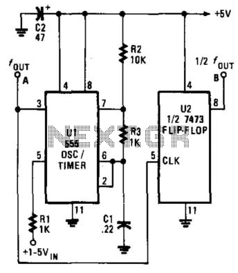
The Voltage-Controlled Oscillator (VCO) has an output frequency that ranges from 1500 Hz at Vcontrol = 1 V to 300 Hz at Vcontrol = 5 V. The resistive component R1 or the capacitive component C1 can be adjusted to...
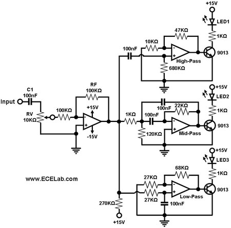
Figure 1 illustrates a simple circuit designed for converting an audio signal (such as one from the output terminals of a CD player). The circuit primarily consists of a buffer/amplifier stage and three filtering circuits: a high-pass filter, a...