
Basic Thyristor Switch
The silicon controlled rectifier (SCR) is a semiconductor device that plays a crucial role in controlling power in electronic circuits. It is a four-layer, three-junction device that can be turned on by applying a small gate current, allowing it to conduct current between the anode and cathode when a specific voltage threshold is surpassed.
In its off state, the SCR behaves like an open switch, blocking current flow. When a positive gate pulse is applied, the device transitions to its on state, allowing current to flow from the anode to the cathode. The SCR remains in this conducting state until the current flowing through it falls below a certain threshold, known as the holding current.
SCRs are widely used in applications such as phase control in AC power circuits, motor speed control, and in rectifiers for converting AC to DC. They are favored for their ability to handle high voltages and currents, making them ideal for industrial applications. Their characteristic switching behavior can be exploited in various power electronics circuits, including inverters, converters, and regulators, enabling efficient energy management and control.
In a typical circuit schematic involving an SCR, the device is represented by a symbol that includes three terminals: the anode (A), cathode (K), and gate (G). The gate terminal is connected to a control circuit that provides the necessary trigger signal to turn on the SCR. Protection components such as snubber circuits may also be included to safeguard against voltage spikes and transients, ensuring reliable operation in demanding environments.
Overall, the SCR is a versatile component in modern electronics, providing efficient control over electrical power in a wide range of applications.The silicon controlled rectifier (S.C.R.) is called as the thyristor. It is like a diode, when the cathode is negative with respect to the anode, the current.. 🔗 External reference
Related Circuits
This design was created to address a challenge with the tailwheel doors of the P-51 Mustang. The issue arises from the complex undercarriage sequence, which would necessitate two independent sequencers. The closing sequence involves the main gear doors opening,...
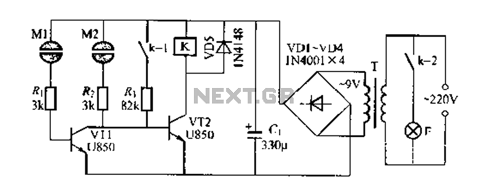
The Darlington circuit is a double-clamp touch switch circuit that features a touch-sensitive sheet and operates with a 20V AC mains supply through an isolated power transformer, ensuring relative safety. Once powered, a 20V optional AC transformer (T) is...
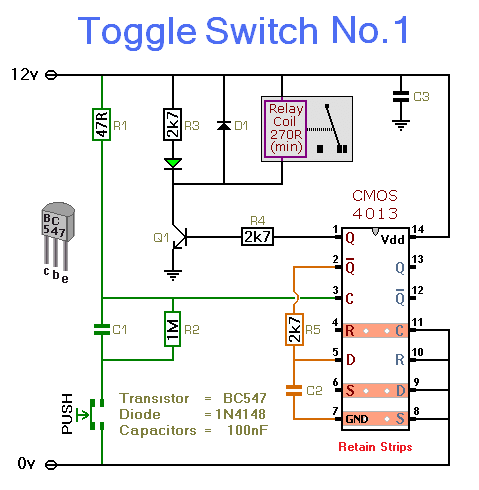
This circuit energizes and de-energizes a relay with the push of a button. Any momentary push-to-make switch can be utilized. Pressing the button once energizes the relay, while pressing it a second time de-energizes the relay. The circuit is...
The circuit is designed to provide protection to a DIY switching power supply for car amplifiers by shutting down under any or all of the three modes of protection (over voltage, under voltage and over temperature) with minimal components. The...
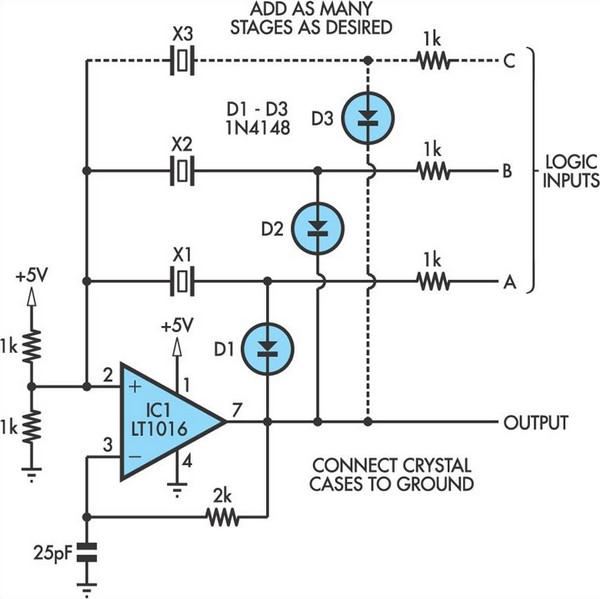
This oscillator circuit allows crystals to be electronically switched through logic commands. The circuit is best comprehended by initially disregarding all crystal components. The oscillator circuit described functions as a frequency generator that utilizes the properties of quartz crystals to...
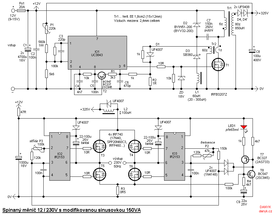
The inverter is designed for powering mains appliances using battery sources. It functions as a switching converter, eliminating the need for bulky, heavy, and costly iron transformers. This design provides advantages such as compact size, lightweight construction, precise output...
Warning: include(partials/cookie-banner.php): Failed to open stream: Permission denied in /var/www/html/nextgr/view-circuit.php on line 713
Warning: include(): Failed opening 'partials/cookie-banner.php' for inclusion (include_path='.:/usr/share/php') in /var/www/html/nextgr/view-circuit.php on line 713