
Simple Dc/Ac Inverter Circuit

The circuit functions by converting direct current (DC) into alternating current (AC) using the 555 timer as an oscillator. The 555 timer is configured in astable mode, generating a square wave output that oscillates between high and low states. This output drives the buffer amplifier, where transistors Q1, Q2, and Q3 amplify the signal to a suitable level for driving the transformer.
The choice of transformer T1 is critical, as it determines the output voltage and current characteristics of the inverter. A 6.3-V transformer is typically used for low-power applications, while a 12.6-V transformer can be employed for higher power needs. The output frequency of the inverter is predominantly determined by the timing components R1 and C1. By adjusting these components, the user can fine-tune the frequency to match specific requirements of the load being powered.
The design of this inverter is advantageous for applications requiring low-cost and lightweight solutions for AC power generation from a DC source. It is commonly used in small electronic devices, battery-operated equipment, and other applications where a compact inverter is necessary. The simplicity of the circuit allows for easy troubleshooting and modifications, making it a popular choice among hobbyists and engineers alike. This dc-to-ac inverter is based on the popular 555. A 555 oscillator circuit drives a buffer amplifier consisting of Ql, Q2, and Q3. The circuit operates at 150 to 160 Hz. Tl can be a 6.3-V or 12.6-V filament transformer as applicable. The frequency can be changed by changing the values of Rl and/or Cl.
Related Circuits
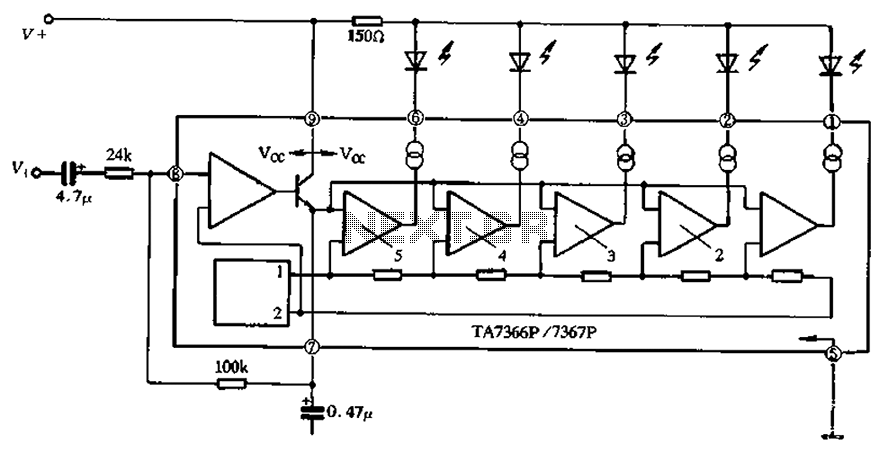
The TA 7366/7367 is a commonly used single display driver circuit manufactured by Toshiba Corporation. It features a 5 LED driver circuit and is designed in a 9-pin single in-line plastic structure. The circuit configuration includes an operational amplifier...
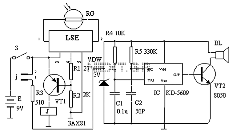
The circuit principle is illustrated in the accompanying figure. When the night light shines on the photosensitive resistor RG, it exhibits a high resistance (significantly greater than 50K). As a result, the output of the LSE pin is low,...
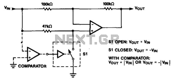
The operational amplifier (op amp) can function as either an inverter or a buffer, depending on the polarity controlled by a switch. When configured as a buffer, the gain remains constant at 1. In contrast, when functioning as an...
Figure 2-32 (a) illustrates the time control diagram for a motor operated by switch S1. When S1 is set to position 1, the power driver circuit supplies current to the motor, enabling it to run. When S1 is switched...
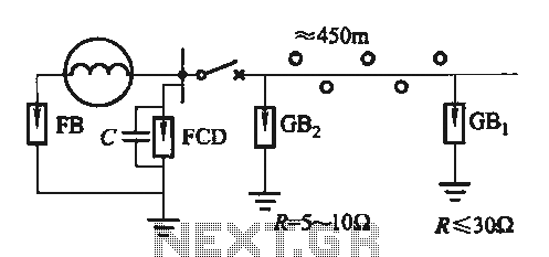
Direct distribution lightning generator with a capacity range of 300 to 1500 kW, designed for single-phase applications. The generator facilitates the direct distribution of electrical energy, providing reliable performance for various applications. The lightning generator operates within a specified power...
The IR Jammer is a fun project that provides a bit of safe, non-destructive fun. The Infrared Remote Control Jammer allows you to render all IR remote controls inoperative! The microcontroller in this design allows for all 6 of...