
Simple Discrete Logic Probe

The logic probe circuit is a fundamental tool in electronics, serving to indicate the logical state of a digital signal at various points within a circuit. The circuit typically consists of a few key components: a power supply, a resistor, a diode, and an LED (Light Emitting Diode).
When the probe tip is connected to a point in the circuit, the circuit must be powered. If the point is at a high state (usually representing a logical '1'), the voltage at that point will exceed a certain threshold, allowing current to flow through the circuit. This current passes through the resistor and the LED, causing the LED to illuminate, indicating a high state.
Conversely, if the point is at a low state (representing a logical '0'), the voltage will be insufficient to forward bias the diode, and the LED will remain off, indicating a low state.
To enhance the functionality of the logic probe, additional features can be integrated. These may include a built-in buzzer that sounds when a high state is detected or a switch that allows the user to select between different voltage thresholds for testing. The design may also incorporate a multi-colored LED to provide more intuitive feedback, such as green for high and red for low.
The logic probe circuit is essential for troubleshooting and verifying the operation of digital circuits, making it an invaluable tool for engineers and hobbyists alike. Proper understanding and implementation of this circuit can aid in the efficient diagnosis of circuit issues, ensuring reliable performance in electronic systems.This is simple logic probe circuit. Logic probe is used to determine if a point in a circuit has high or low state when the circuit is in operation.? Here is. 🔗 External reference
Related Circuits

The lower schematic represents a standard bidirectional rectifier along with capacitors and a 7805 voltage regulator, which provides a stable 5V source to power the electronic components of the frequency counter. A fuse is included for security purposes. The...
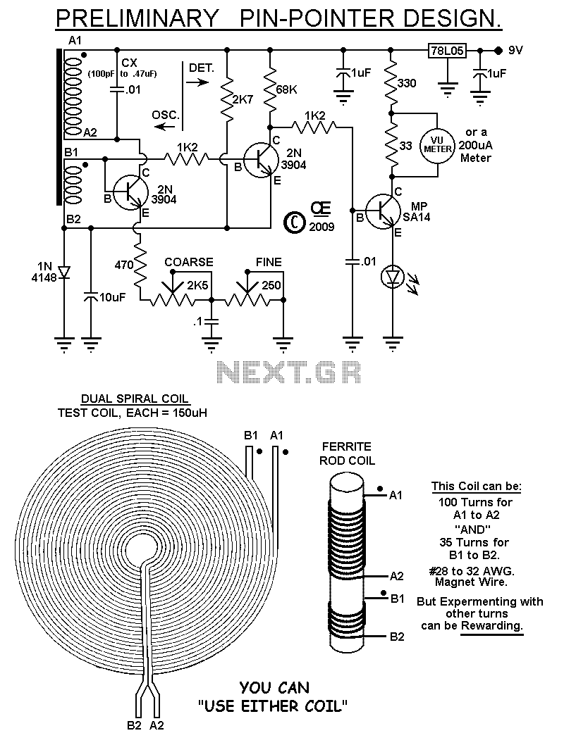
The Meter and other small circuit differences, gives better performance. On the Schematic, I show Two Possible Coils. 1) The Ferrite Rod, creates an Accurate Pin Point. But it also has a Very Narrow Detection Field. 2) The Dual Wound "Tesla Coil"...
This circuit is not a novelty, but it proved so useful, simple and cheap that it is worth building. When the positive (Red) probe is connected to a DC positive voltage and the Black probe to the negative, the...
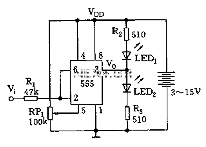
Figure 555 illustrates a simple logic circuit test lead. The test pen utilizes the 555 timer IC as its core component, incorporating a Schmitt trigger to assess the logic state of digital circuits. The circuit has two outputs: when...
Trimming is straightforward when matched NPN transistors are utilized for Q1 and Q2, along with 1% tolerance resistors for R6 to R11. A dual trace oscilloscope, digital voltmeter (DVM), and sine wave generator are required for this process. Although...
This circuit is a simple analog multiplier. The operation of the circuit can be understood by considering A2 as a controlled gain amplifier. It involves components such as an analog multiplier, a log-antilog circuit, and a summing junction, along...