
Simple Door Intercom

The intercom circuit described operates by utilizing a dual-function speaker system, where the same components serve as both microphones and loudspeakers. This design simplifies the circuit while maintaining functionality. The core components typically include an audio amplifier, a power supply, and a control mechanism to switch between microphone and speaker modes.
The audio amplifier is essential for boosting the audio signals captured by the microphone when someone presses the doorbell. The amplified signal is then transmitted through the speaker, allowing for clear communication. The circuit may also include a simple push-button switch connected to the doorbell, which activates the intercom system when pressed.
In terms of power supply, a low-voltage DC source is often used to ensure safety and efficiency. The circuit can be powered by batteries or a wall adapter, depending on the installation requirements. Additionally, the design may incorporate capacitors and resistors to filter noise and stabilize the audio signals, ensuring high-quality sound transmission.
Overall, this intercom circuit is an effective solution for doorbell communication, leveraging the dual functionality of speakers to create a compact and efficient system. Adjustments can be made to enhance performance, such as integrating additional features like volume control or LED indicators for visual feedback.This intercom circuit suitable for accompanying door bell. This circuit uses the speakers both as microphones and as loudspeaker. This intercom is made.. 🔗 External reference
Related Circuits
The door alarm is designed to be mounted on the door handle and emits a beep when someone touches the door handle from the outside. The door alarm circuit operates on the principle of detecting physical contact with the...
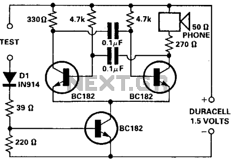
This tester is designed for tracing wiring on Printed Circuit Boards (PCBs). Resistors below 50 ohms function as a short circuit, while those above 100 ohms behave as an open circuit. The circuit utilizes a simple multivibrator activated by...

This document contains a simple calculator and PCB circuit board wiring diagram, allowing interested students to design their own. The schematic for the simple calculator circuit typically includes a microcontroller, a keypad for user input, and a display for output....

This circuit sets the time using a simple model that can accurately maintain the time over extended periods. It employs the CA3140 integrated circuit for its functionality. The circuit utilizes the CA3140 operational amplifier, which is known for its high...
The following circuit illustrates the SCR BRY35 used in a simple radio control circuit. Features include a straightforward and efficient receiver for operation. The SCR BRY35 is a silicon-controlled rectifier designed to facilitate the control of high-power loads through low-power...
A simple NiCd charger can be constructed using commonly available components and an inexpensive LM317 or 78xx voltage regulator. It incorporates a current limiter made up of resistor R3 and a transistor, allowing it to charge multiple cells until...