
SIMPLE EVENT COUNTER

The circuit described consists of several key components designed to function together in a basic counting application. S1 acts as the main power switch, controlling the overall power supply to the circuit. When S1 is in the ON position, the circuit is powered and ready for operation.
The component U2 is responsible for generating a pulse signal. This pulse is triggered when switch S2 is pressed. The pulse generated by U2 serves as an input signal to counter U3, which is a one-digit counter integrated circuit (IC). The primary function of U3 is to count the number of pulses it receives from U2. Each pulse corresponds to an increment in the count displayed by the circuit.
U4 and DISP1 are crucial components for monitoring the output of counter U3. U4 is likely an interface that interprets the digital count from U3, while DISP1 serves as the display unit that visually presents the count to the user. This setup allows for easy observation of the count value in real-time.
Additionally, S3 functions as a reset switch that allows the user to reset the count displayed on DISP1 back to zero. This feature is essential for applications where the count needs to be restarted or cleared for a new counting session.
Overall, this circuit serves as a simple yet effective one-digit counting mechanism, suitable for various applications where a basic count is required. Its design emphasizes ease of use with a straightforward reset function and a clear display of the current count.S1 is a power switch. U2 drives counter U3 by producing a pulse when S2 is depressed. U4 and DISP1 read the count of counter IC U3. S3 is a reset to zero switch. The counter is a basic one-digit circuit useful as a holding block or by itself. 🔗 External reference
Related Circuits

Metronome is an electronic device that keeps rhythm by making regulated clicking sounds, device used to keep the beat while playing a musical instrument. The circuit is an old design to build, but you will find it useful. The metronome...
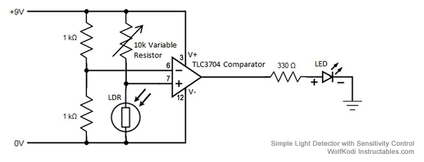
The schematic diagram for the circuit is provided in the accompanying image. As indicated by its name, a comparator is designed to compare two specified voltages. The circuit includes a pair of 1K resistors. A comparator circuit typically utilizes operational...
The circuit serves as a foundational design, requiring experimentation for specific applications. In popular microwave bands, local oscillators (LOs) are typically generated using overtone crystal oscillators followed by multipliers. A table presents the standard LO frequencies for narrowband segments,...
This circuit utilizes a 555 timer integrated circuit (IC) as an alarm system designed to deter theft of luggage and prevent unauthorized entry into homes. The alarm is activated when a thin wire, typically as fine as a human...
This is a design circuit for a simple function generator. Built around a single 8038 waveform generator IC, this circuit produces sine, square, or triangle waves from 20Hz to 200kHz in four switched ranges. There are both high and...
This transmitter operates on a 9-V battery and can function as a wireless microphone compatible with standard 88- to 108-MHz FM broadcast receivers. To adhere to FCC regulations, the antenna length should not exceed 12 inches. The inductor L1...