
Theft preventer alarm

The circuit primarily consists of a 555 timer IC, resistors, capacitors, a speaker or buzzer, and a thin wire that serves as a triggering mechanism. In the astable mode, the 555 timer continuously oscillates between its high and low states, generating a square wave output. This output can be connected to a piezoelectric buzzer or speaker, which converts the electrical signal into audible sound.
The triggering mechanism involves placing a thin wire in a position where it can be easily disrupted by unauthorized access. When the wire is broken, it alters the voltage levels at the input of the 555 timer, causing it to transition from a low state to a high state, thereby activating the output. The resistors and capacitors in the circuit determine the frequency and duty cycle of the oscillation, which can be adjusted to change the sound frequency produced.
Power supply considerations are crucial for this circuit. It typically operates on a DC voltage source, which can be a battery or an external power supply. Proper selection of components is essential to ensure reliable operation and to prevent false alarms due to environmental factors.
This alarm system can be further enhanced by incorporating additional features such as LED indicators to signal activation, or a delay circuit to prevent accidental triggering. Overall, this simple yet effective alarm circuit can serve as a valuable deterrent against theft and unauthorized entry.This circuit utilising a 555 timer IC can be used as an alarm system to prevent the theft of your luggage, burglars breaking into your house etc. The alarms goes ON when a thin wire, usually as thin as a hair is broken. The circuit is straightforward. It uses a 555 IC wired as an astable multivibrator to produce a tone of frequency of about 1kHz w hich gives out a shrill noise to scare away the burglar. 🔗 External reference
Related Circuits
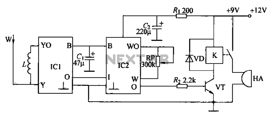
A circuit for an inductive burglar alarm is derived from a radio scanning detection circuit, which includes a signal processing circuit and an alarm circuit. The radar detection circuit module consists of components such as microwave emission, low-pass filtering,...
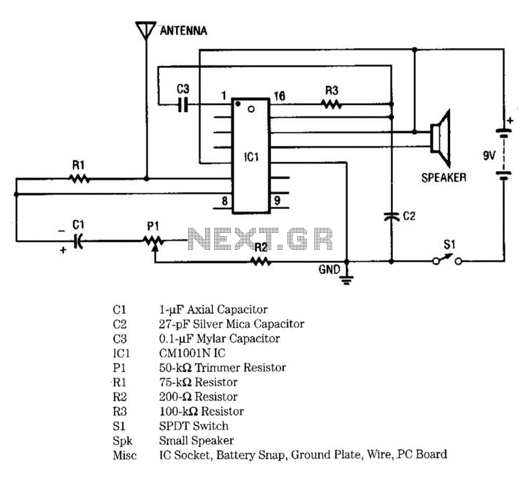
IC1 includes multiple oscillators and an amplifier. The low-frequency audio signal oscillator provides an input to the amplifier. This signal is the audio tone that is amplified and subsequently delivered to the speaker by the amplifier. The high-frequency oscillator...

The alarm can be utilized for various applications, including frost monitoring and room temperature monitoring. In its quiescent state, the circuit consumes only a few microamperes, allowing a 9 V dry battery (PP3, 6AM6, MN1604, 6LR61) to potentially last...
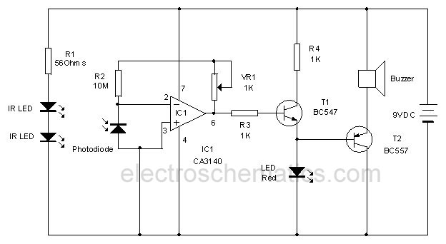
This infrared alarm barrier is designed to detect individuals passing through doorways, corridors, and small gates. The transmitter emits an infrared light beam that is not visible to the human eye. When the beam is interrupted by a person,...
This project features a schematic for a touch alarm circuit. The circuit is highly sensitive and activates a piezo buzzer or any other type of buzzer, along with an LED, for a predetermined duration when a metal plate is...

The circuit automatically activates when the car is turned off, providing a variable time for the user to exit and secure the vehicle. It also offers a variable time delay for entering and starting the car. The 555 oscillator/timers...