
Simple FM transmitter powered by 1.5V battery

This FM transmitter circuit operates on the principle of frequency modulation, which allows for the transmission of audio signals over radio waves. The core component, a single transistor, serves as the active element that amplifies the modulated signal generated by the L-C circuit. The L-C circuit, composed of the inductor L1 and a variable capacitor, defines the operating frequency of the transmitter.
The inductor L1 is constructed with 8 turns of #22 AWG wire, which is a standard gauge for RF applications, ensuring adequate inductance while maintaining manageable resistance. The physical dimensions of the inductor, specifically the 4-5 cm diameter, are crucial as they influence the inductance value and, consequently, the resonance frequency of the circuit.
The antenna, a 6-inch copper wire, is critical for effective transmission, as it radiates the modulated signal into the surrounding environment. The placement of the antenna at the midpoint of the inductor enhances the coupling between the inductor and the antenna, optimizing the efficiency of the transmission.
Resistors used in this circuit are rated at 1/4 watt, suitable for low-power applications, and should be selected based on the desired biasing and gain characteristics of the transistor. Capacitors are primarily ceramic, known for their stability and reliability in RF circuits, with the exception of the electrolytic capacitor, which is used for power supply filtering. The inclusion of a trimmer capacitor allows for fine-tuning of the frequency, facilitating adjustments to meet specific transmission requirements.
It is imperative to adhere to legal regulations concerning FM transmission power levels, as exceeding these limits can lead to legal repercussions. The Federal Communications Commission (FCC) establishes guidelines to ensure that transmissions do not interfere with licensed broadcasts, and any modifications to increase power capacity should be approached with caution and awareness of these regulations.This simple FM (frequency modulation)transmitter is powered only bya 1. 5V batteryand usesonly 1 transistor. The frequency of this transmitteris controlled by the L-C resonance circuit andoperates from 80 to 110 MHz. The inductor L1 is made of 8 turns of #22AWG magnetic wire wound with thediameter of 4-5cmor diameterof a pencil.
The antenna is a 6inc hes copper wireconnected at the middle of L1 inductor. Other parts arenot critical and can be replacedby its closest value. Resistor are1/4 watttypeandcapacitors are ceramic except the 10uF electrolytic capacitor. 5-60pF capacitor is a trimmer type or variable type. Note: Modifying this simple fm transmitter circuit such as increasing itspowercapacity is illegal. Review the fcc limits regarding fm transmitterif you are planningto build a more powerful one. 🔗 External reference
Related Circuits
%2BCircuit%2Bdiagram%2Busing%2BCD4047%2Band%2BIRFZ44%2Bpower%2BMOSFET.png)
This simple low-power DC to AC inverter circuit converts 12V DC to either 230V or 110V AC. By making simple modifications, it is also possible to convert 6V DC to 230V AC or 110V AC. This inverter can be...
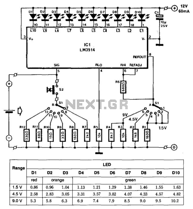
This battery tester utilizes an LM3914 bar-graph driver integrated circuit (IC). Switch SI selects the load on the battery being tested and programs the voltage range. Switch S2 applies the load to the battery under test. A table provides...
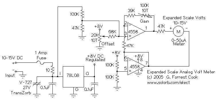
This circuit is used to measure the voltage on a 12V (nominal) lead acid rechargeable battery system. It was specifically designed for use in solar powered systems, but is general enough that it can be used for automotive or...
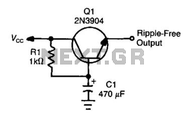
This circuit, often referred to as a capacitance multiplier, is effective for reducing power supply ripple. The capacitance provided by the circuit is equivalent to a capacitor of ( +1) Ci, where Ci represents the capacitance and the gain...
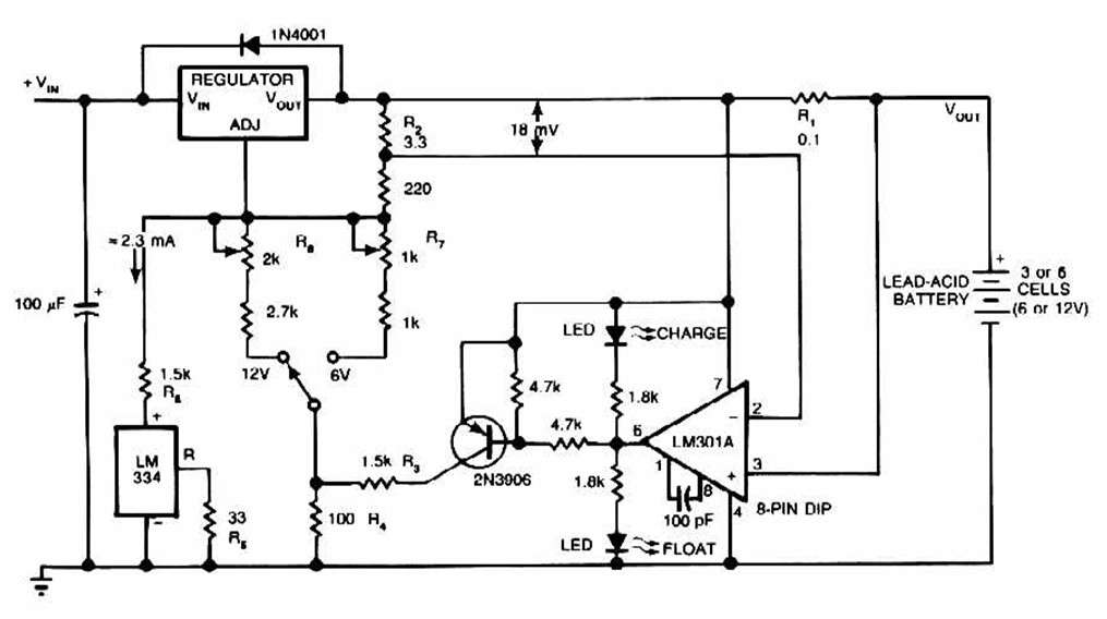
The schematic for this charger is straightforward. It is designed to charge a Gel Cell or other lead-acid types. This simple battery level monitor circuit can indicate the charging process in a 12 Volt lead-acid battery or tubular battery....
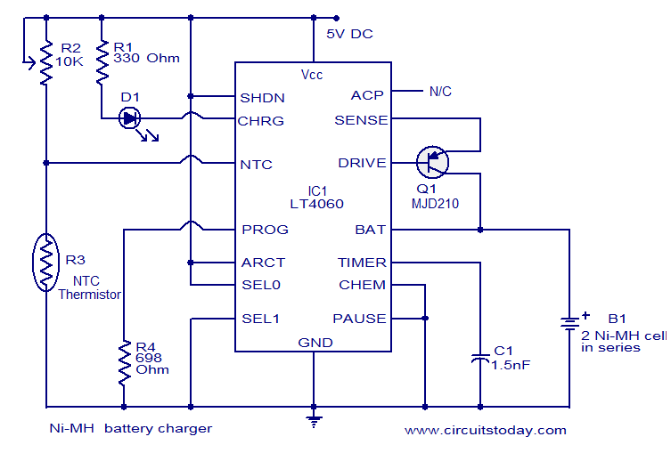
This circuit diagram represents a highly efficient Ni-MH battery charger utilizing the LT4060 integrated circuit from Linear Technologies. The circuit can also accommodate Ni-Cd batteries with minor modifications. To charge Ni-Cd batteries, the CHEM pin (pin 12) of the...