
Simple Ripple Suppressor

The capacitance multiplier circuit utilizes a transistor to enhance the effective capacitance of a capacitor connected at its input. The primary function of this circuit is to filter out voltage fluctuations and noise in the power supply, thereby providing a smoother DC output.
In this configuration, the input capacitor (Ci) is connected to the base of the transistor (Q1), which is typically a bipolar junction transistor (BJT). The collector of Q1 is connected to the output, while the emitter is linked to ground through a load resistor. The gain of the transistor amplifies the capacitance effect of Ci, resulting in an effective capacitance that can be much larger than the physical capacitor used.
The output voltage is taken from the collector of the transistor, and the ripple voltage at this point is significantly reduced due to the increased effective capacitance. This characteristic makes the capacitance multiplier an ideal choice for power supply circuits where space is limited and additional bulk capacitance cannot be used.
In practical applications, the design parameters such as the choice of transistor, the value of Ci, and load conditions must be carefully considered to ensure optimal performance. The circuit can be used in various electronic devices where stable voltage is critical, including audio amplifiers, digital circuits, and other sensitive electronic equipment.
Overall, this circuit provides a compact and efficient solution for improving power supply stability and reducing ripple, leveraging the properties of transistors to achieve enhanced filtering capabilities. This circuit, at times called a capacitance multiplier, is useful for suppression of power-supply ripple. CI provi des filtering that is equal to a capacitor of ( +1) Ci, where = dc current gain of Ql (typically > 50).
Related Circuits
This compact switching power supply utilizes a Schmitt trigger oscillator to control a switching transistor, which delivers current to a small inductor. While the transistor is activated, energy accumulates in the inductor, and upon deactivation, this energy is released...
Simple Surround Sound Decoder. Introduction This surround-sound decoder is based on the Hafler principle, first discovered by David Hafler sometime in the early 1970s. The original idea. The simple surround sound decoder utilizes the Hafler principle to create an immersive...
This involves controlling servo motors through software programming using the PIC 16C71 microcontroller. The input signals range from 0 to 5V. The circuit for controlling servo motors with a PIC 16C71 microcontroller is designed to provide precise control over the...
This is a signal injector designed for individuals who may not have access to extensive test equipment. It can be utilized for tracing audio circuits during troubleshooting or for testing audio circuits that require an input signal. The injector...
A stepper motor controller is required to operate a stepper motor, as a stepper motor cannot function merely by connecting it to a power supply. A stepper motor controller is an essential component for the effective operation of stepper...
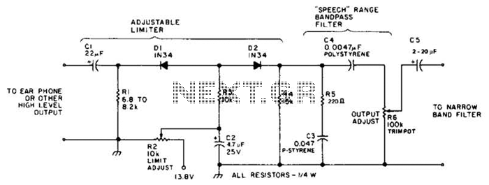
This circuit employs a diode series clipper to limit noise peaks on a received signal. It is most effective in scenarios where several volts peak-to-peak of audio signal are present. The diode series clipper circuit is designed to protect subsequent...